
My Projects
God Bless America!!
Updated:
01/09/10
remove the word SPAM from above email link
![]()
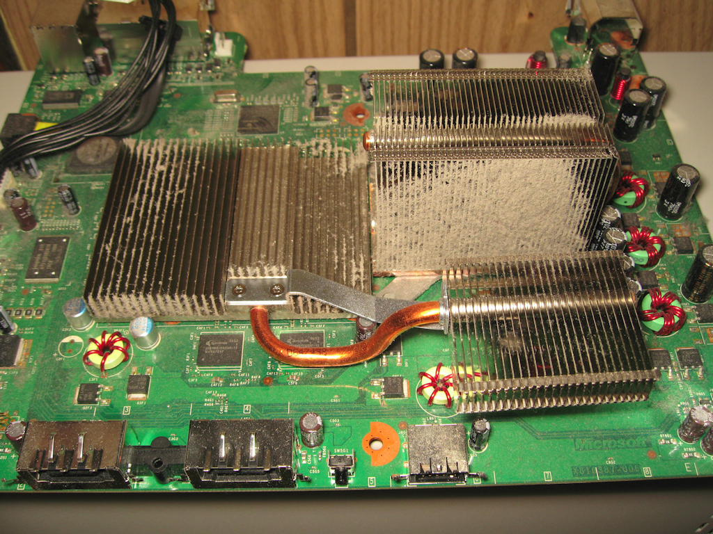
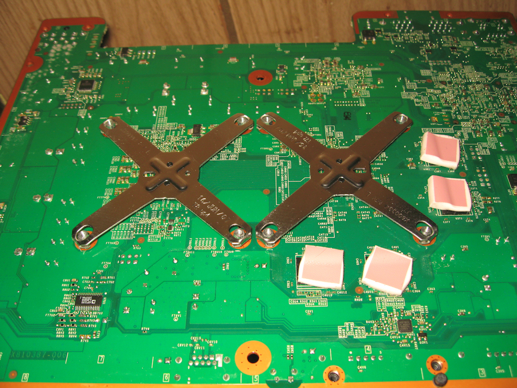
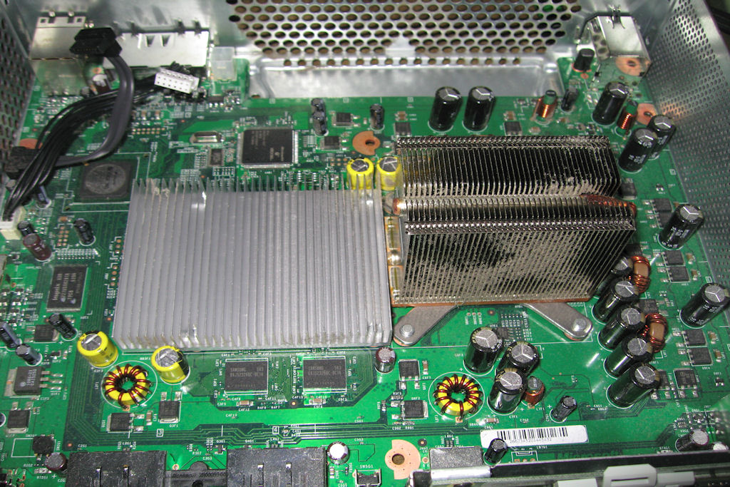
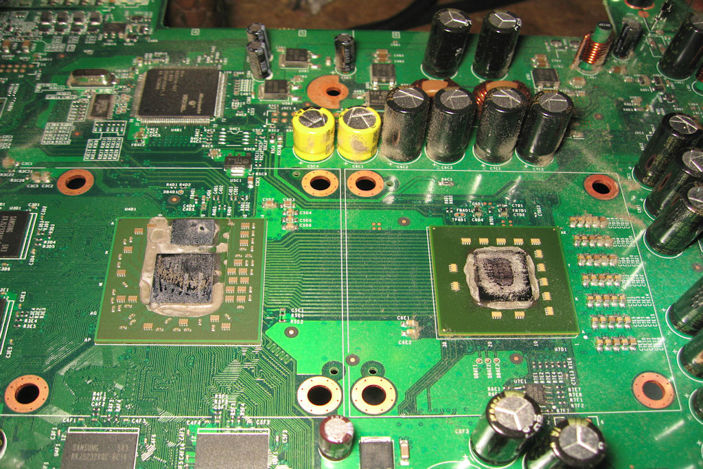
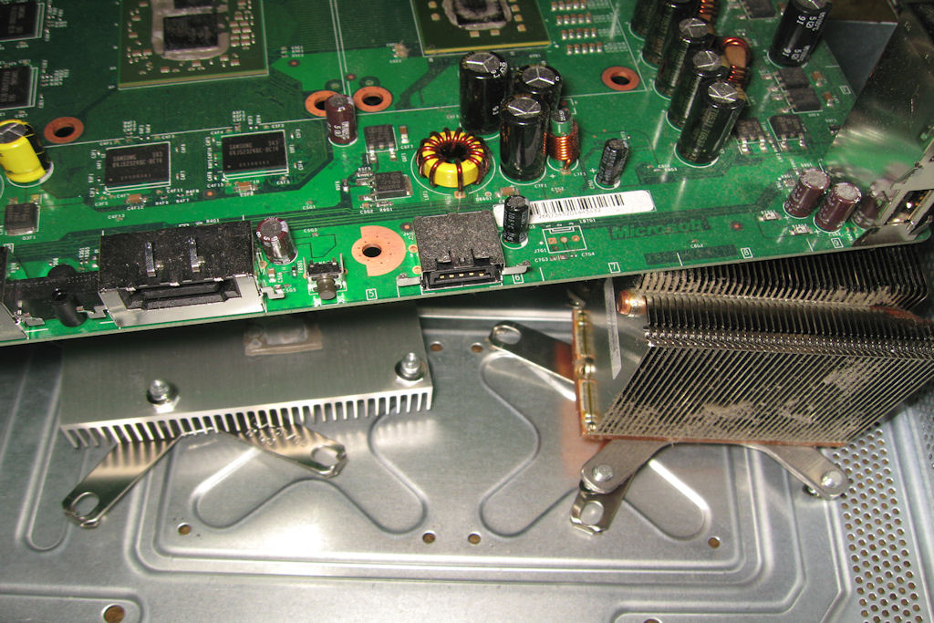
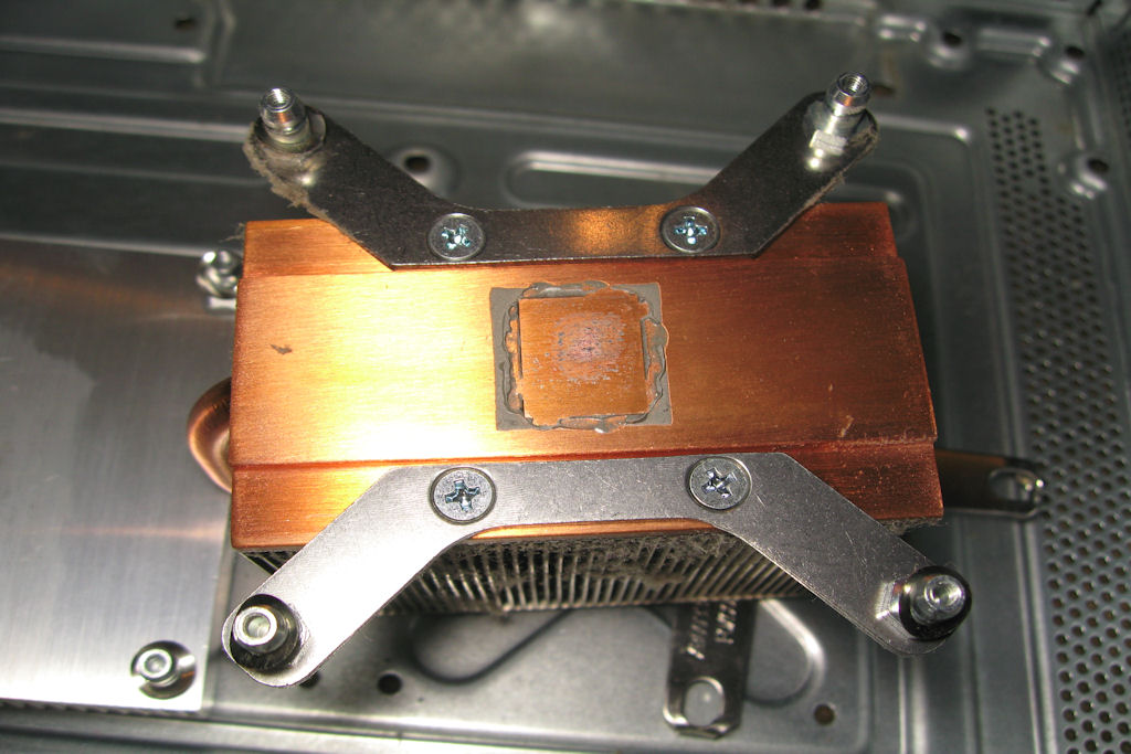
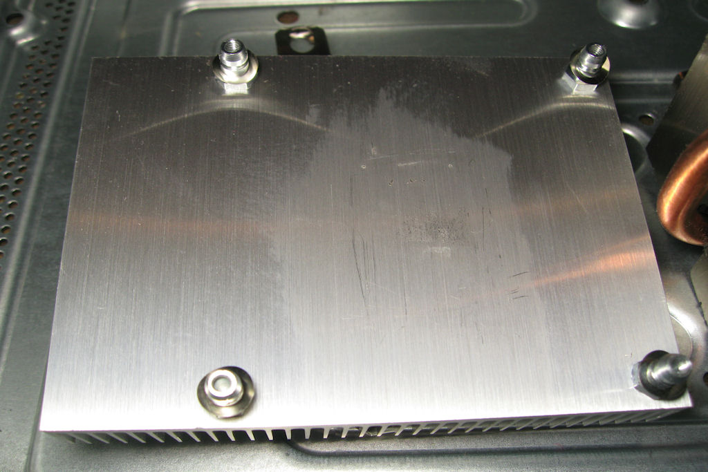
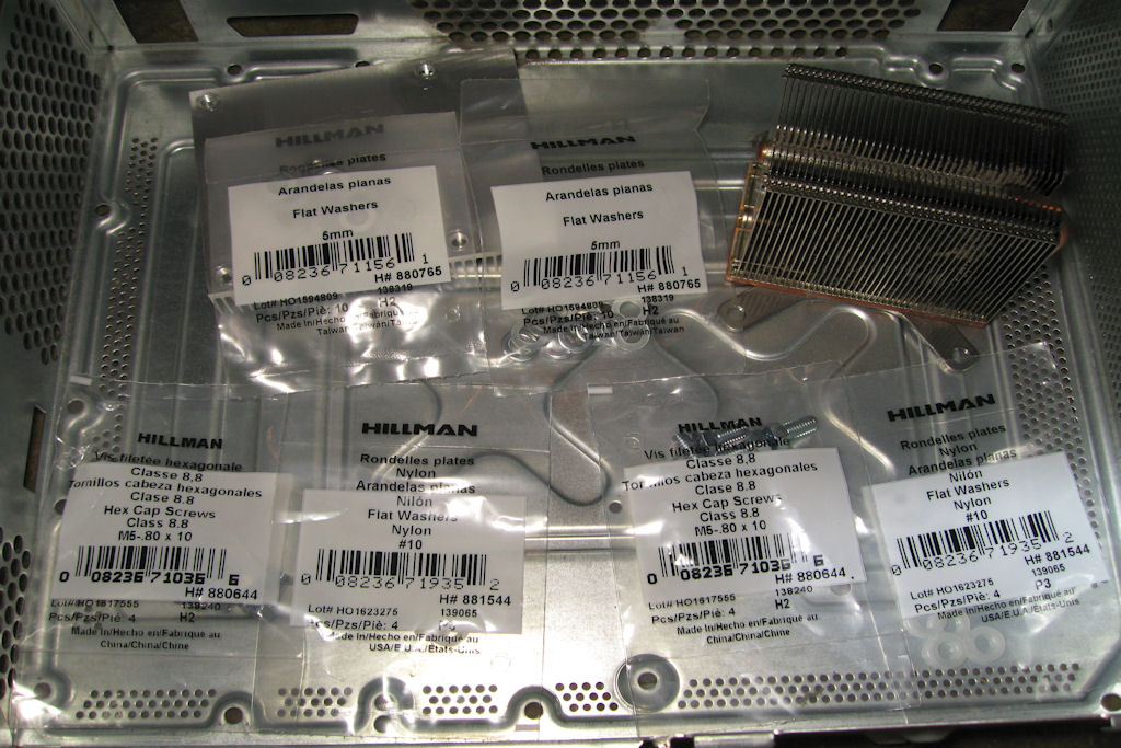
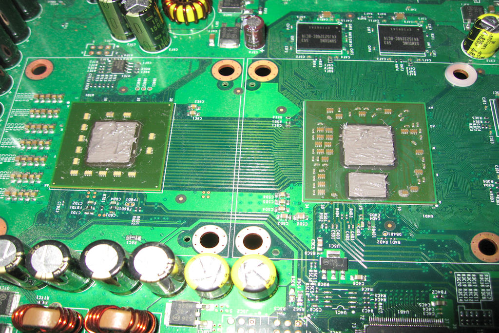
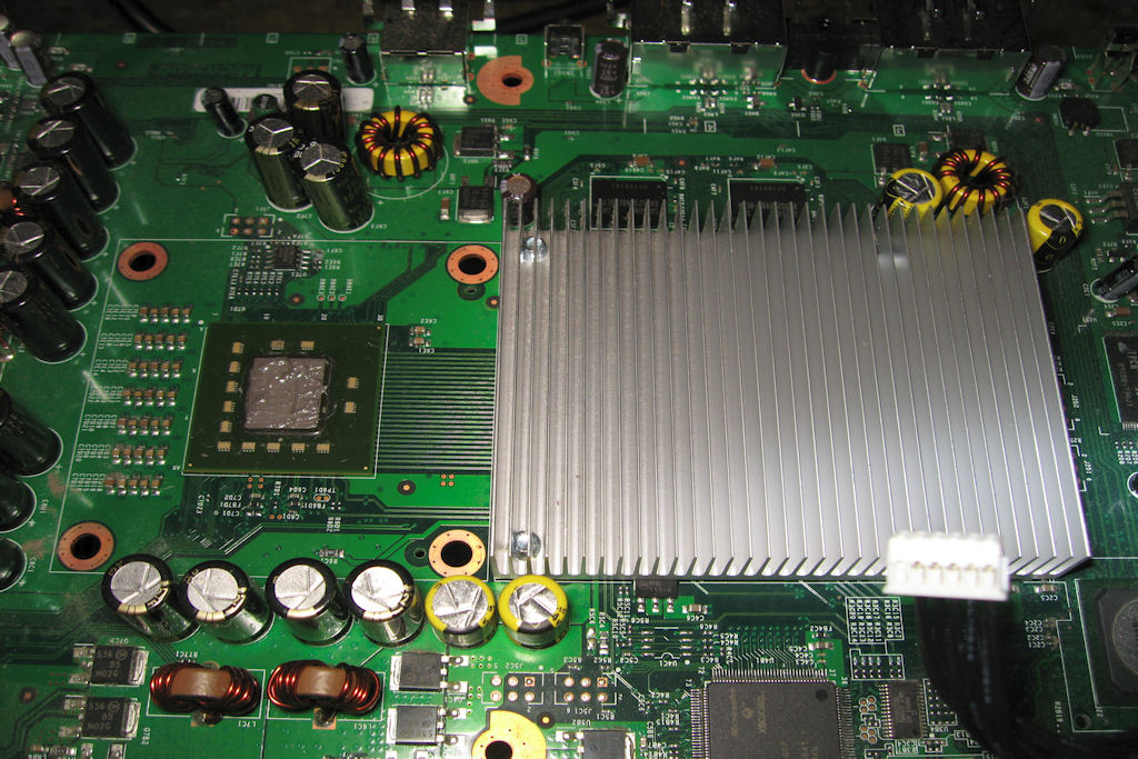
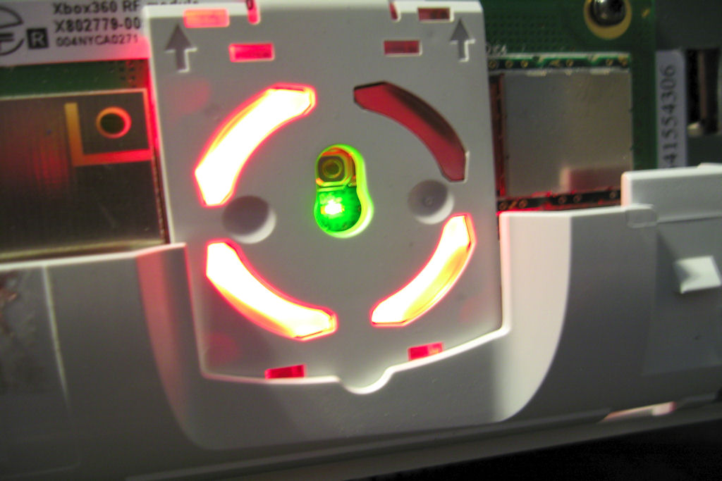
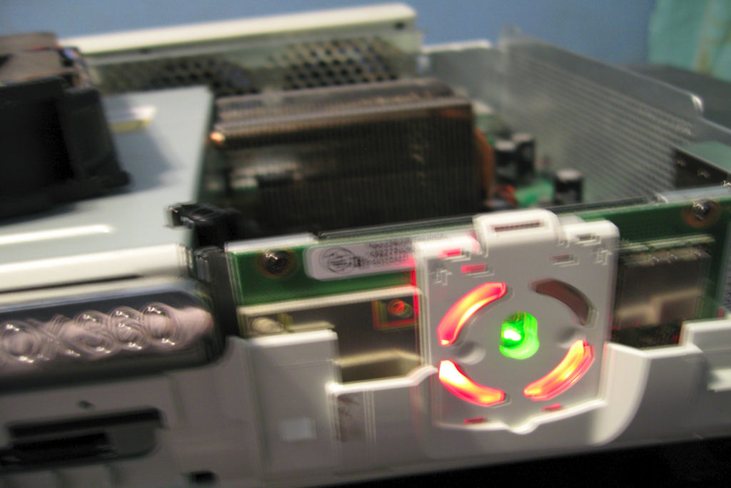
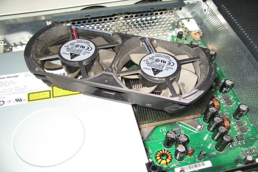
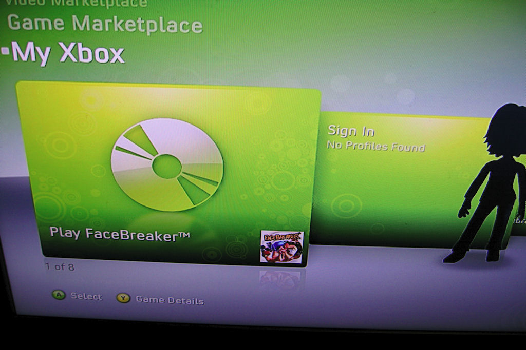
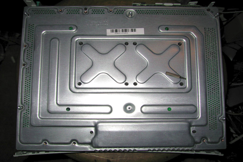
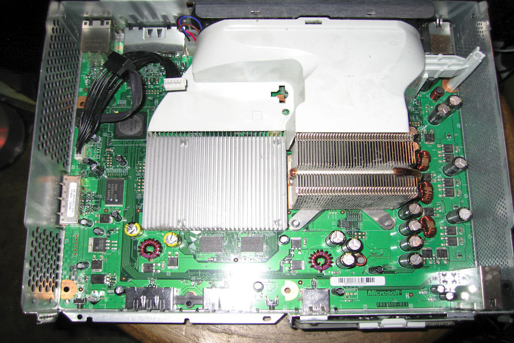
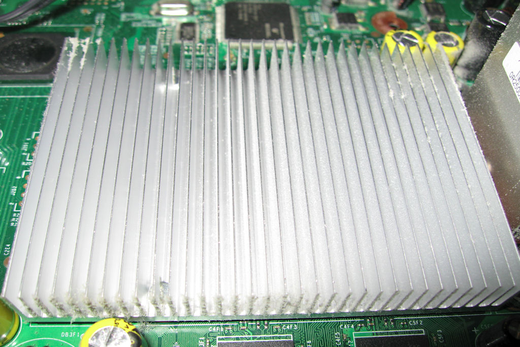
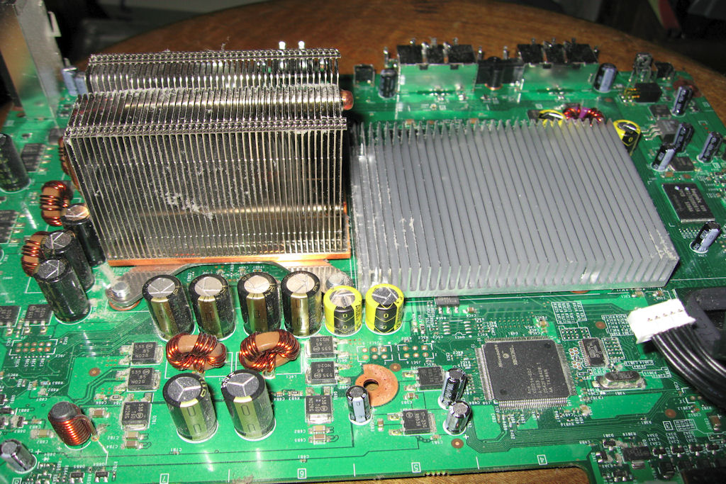
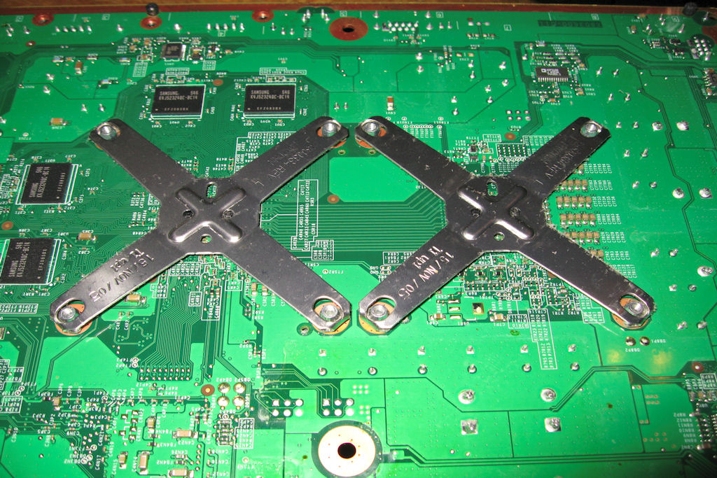
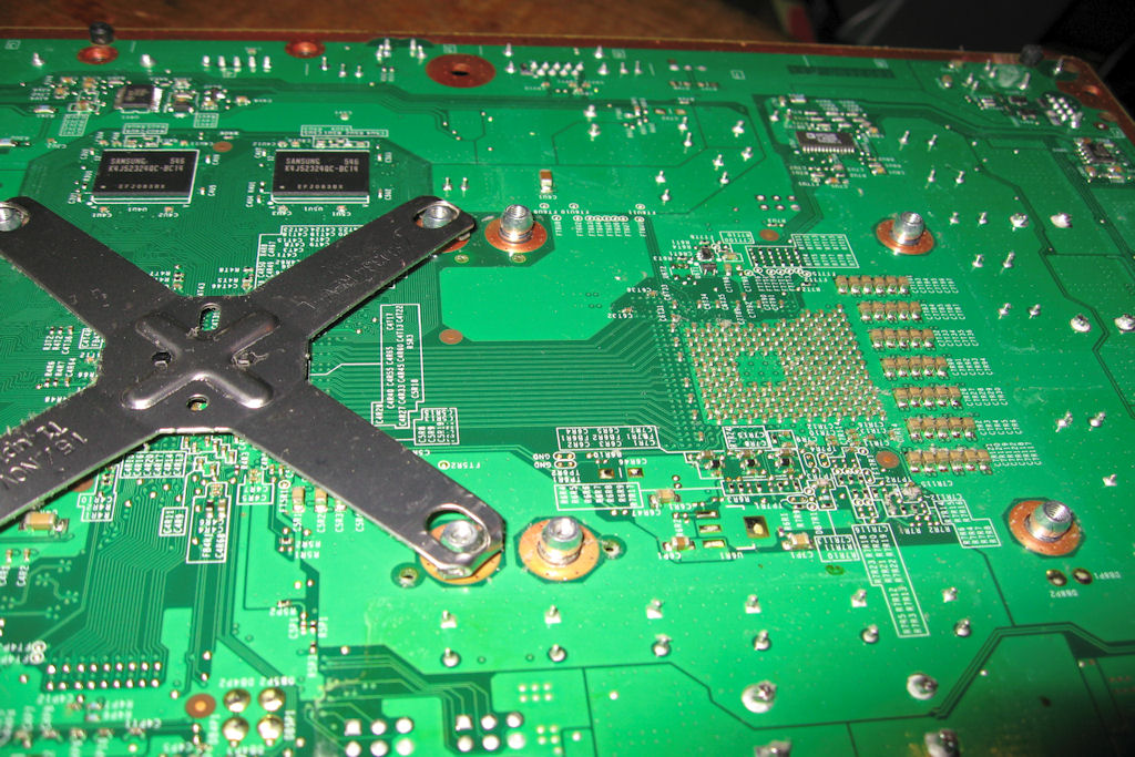
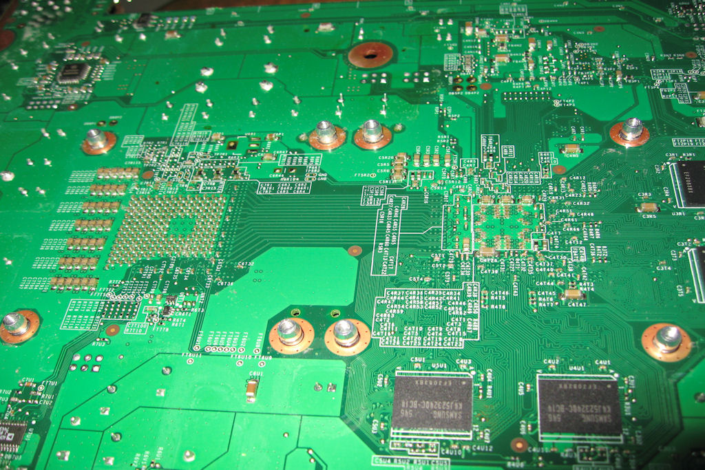
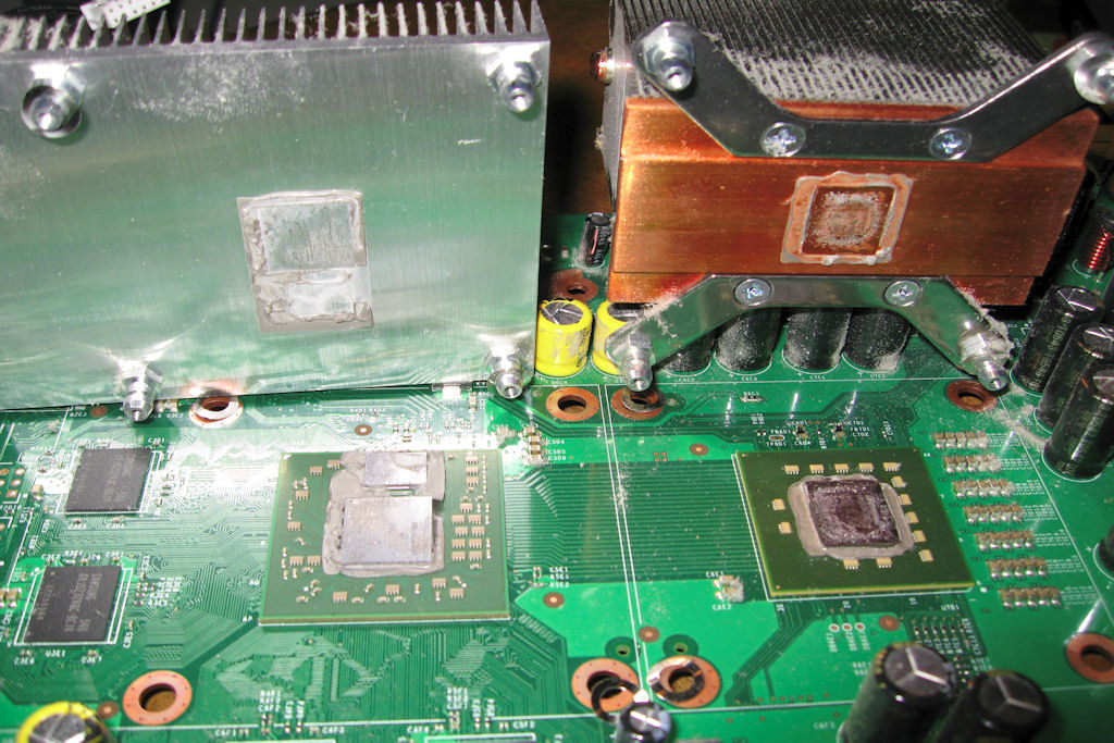
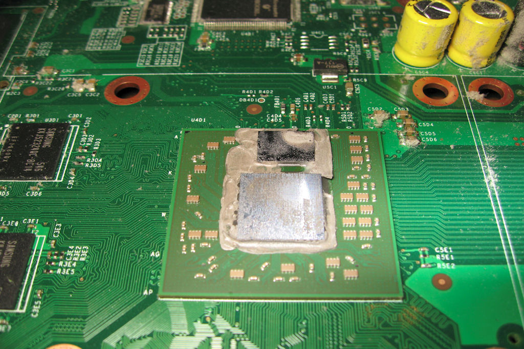
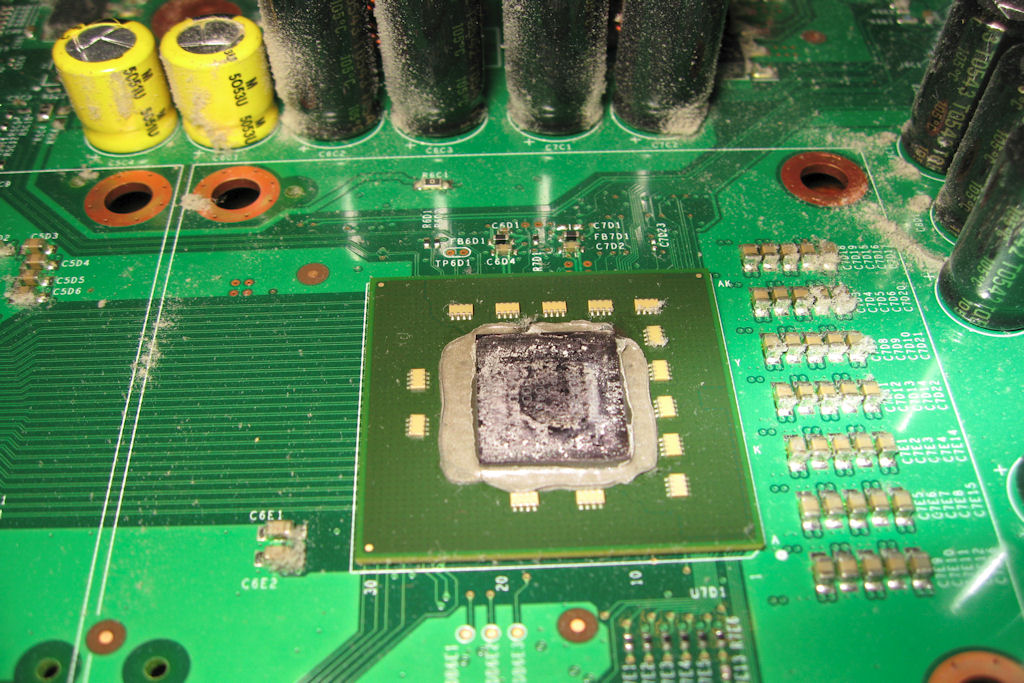
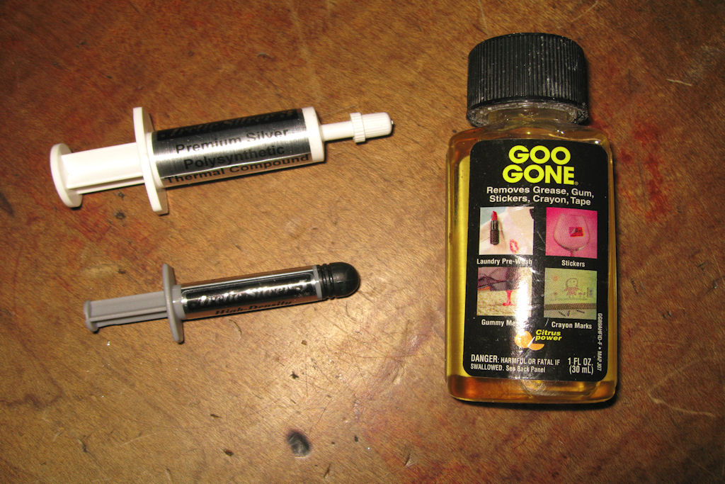
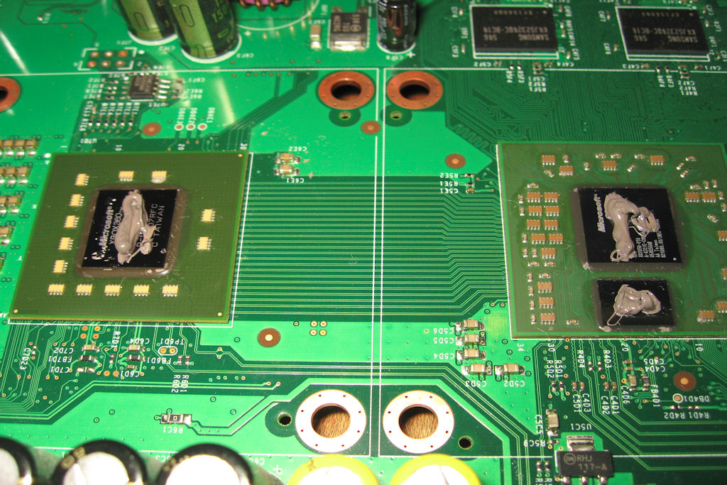
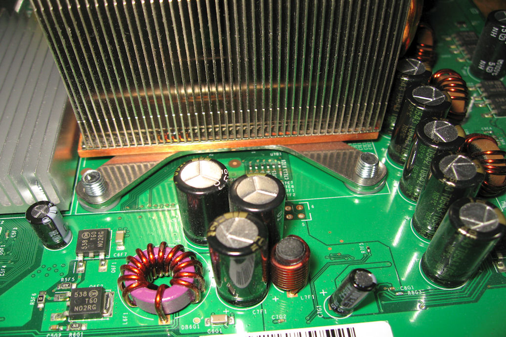
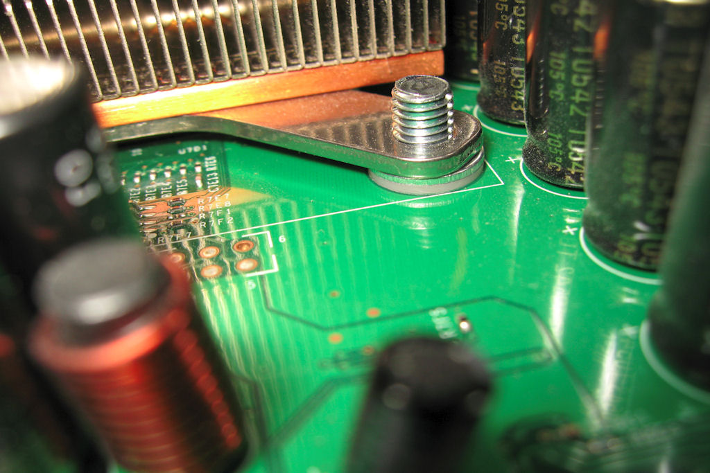
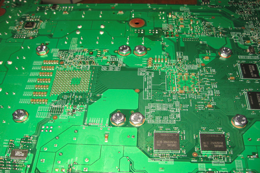
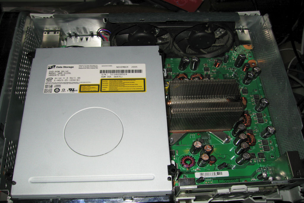
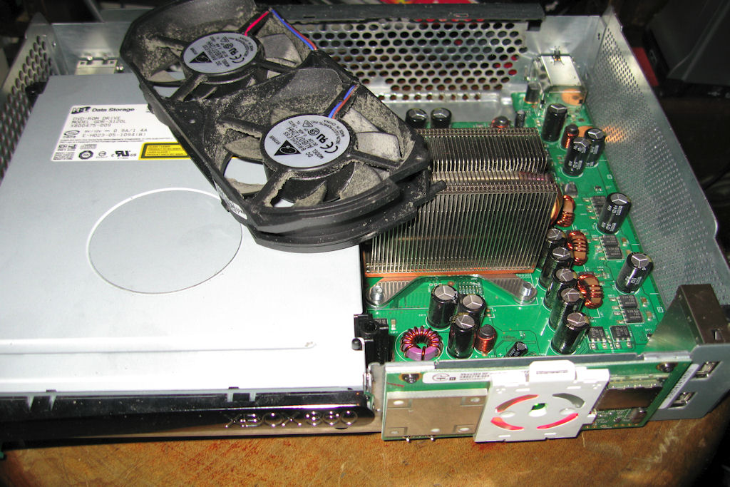
1-05-10
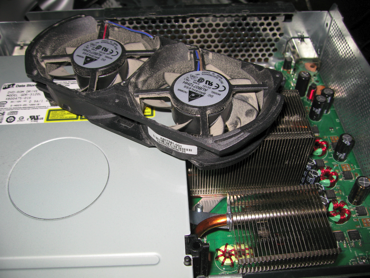
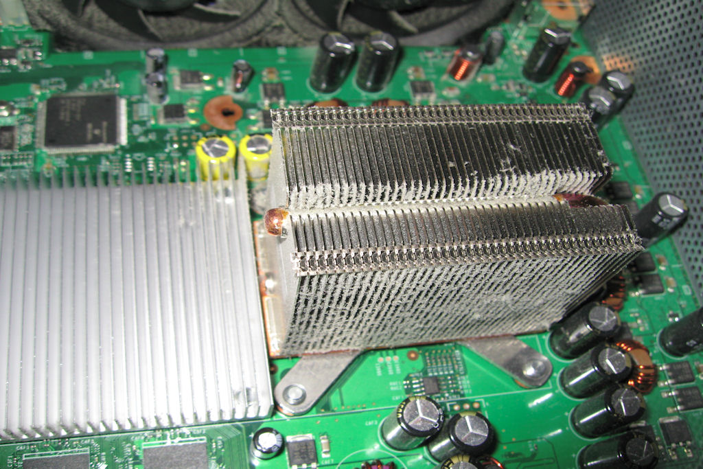
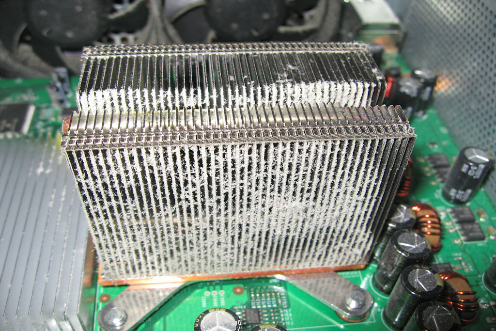
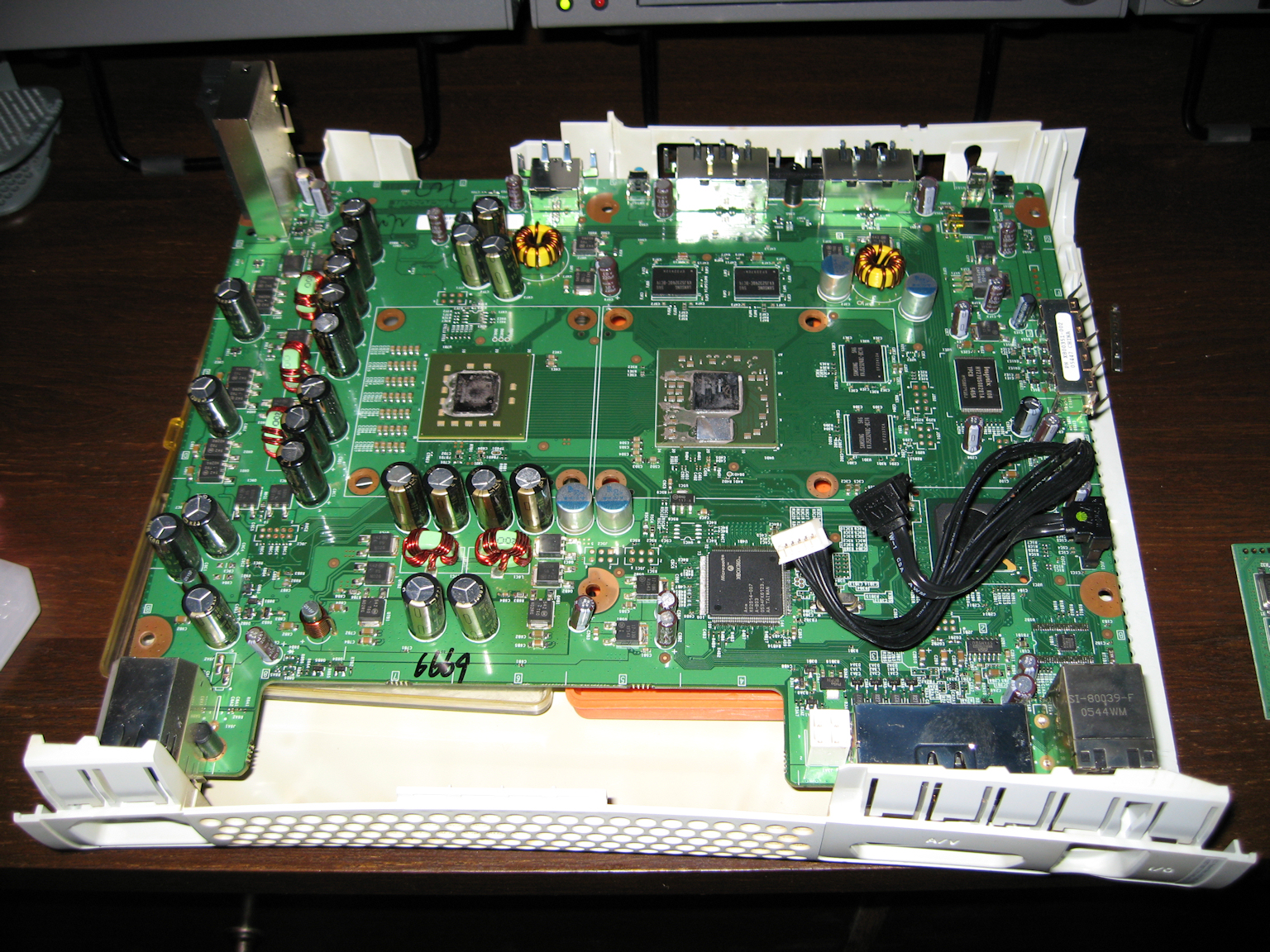
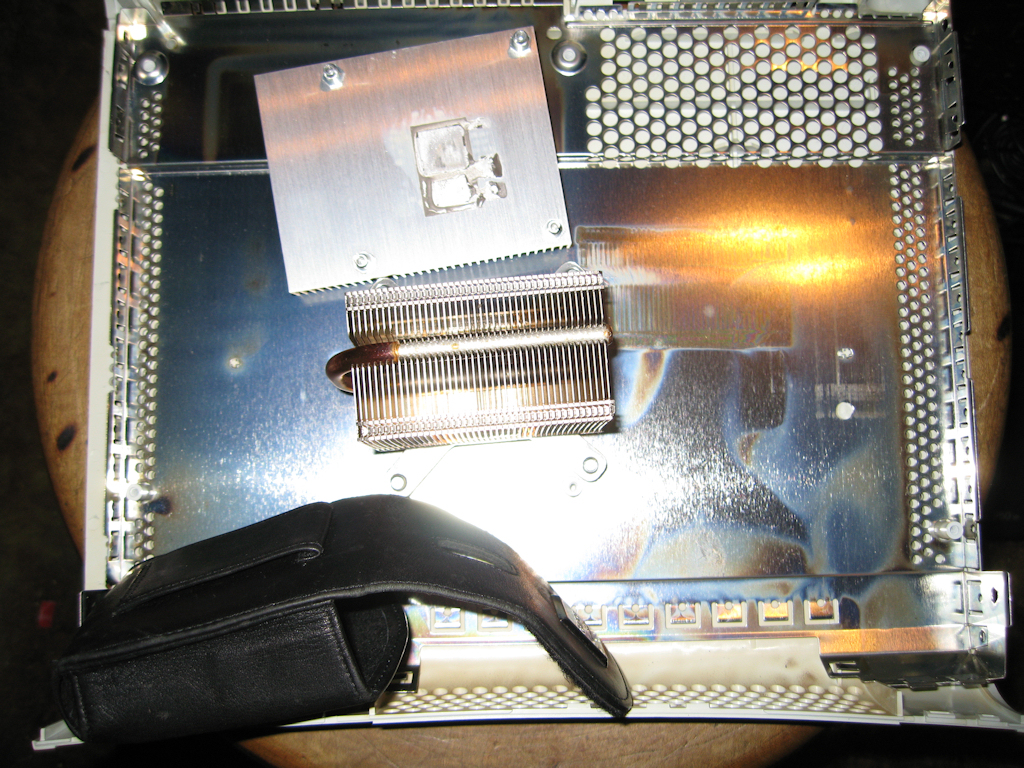
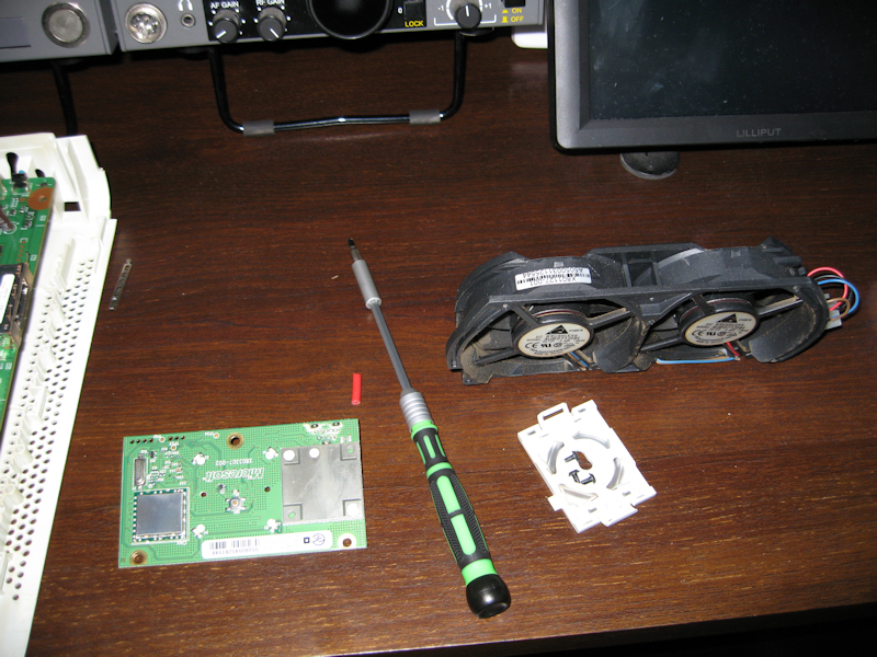
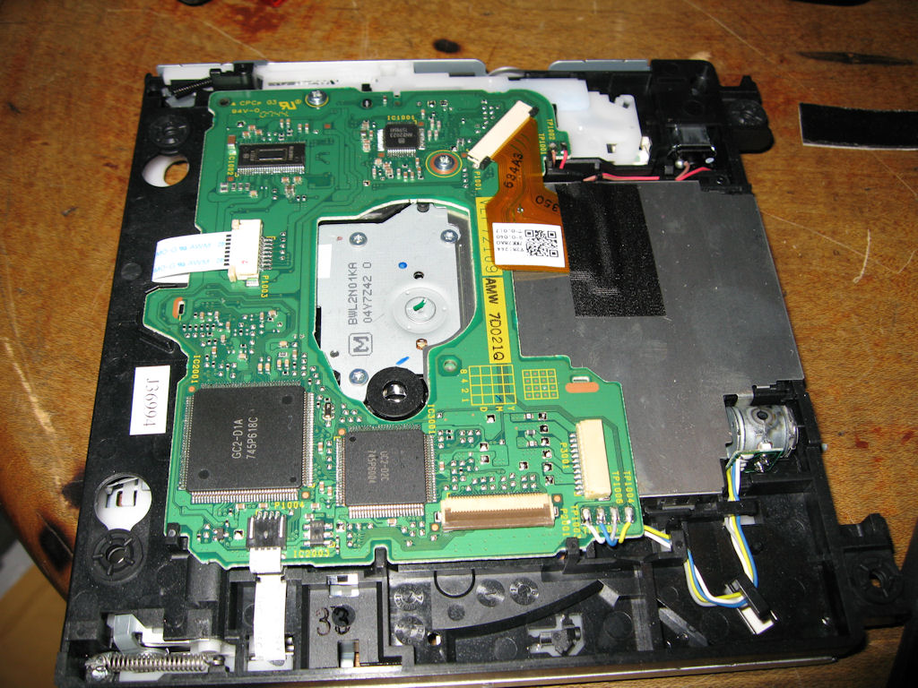
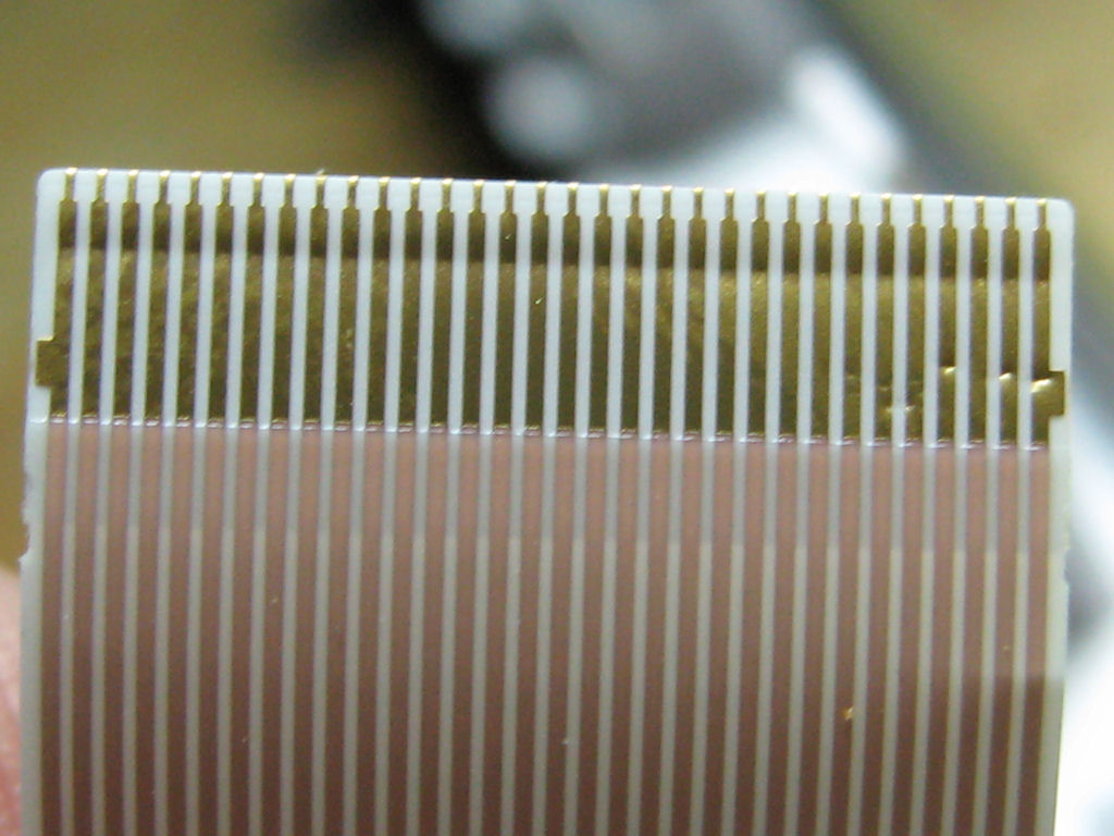
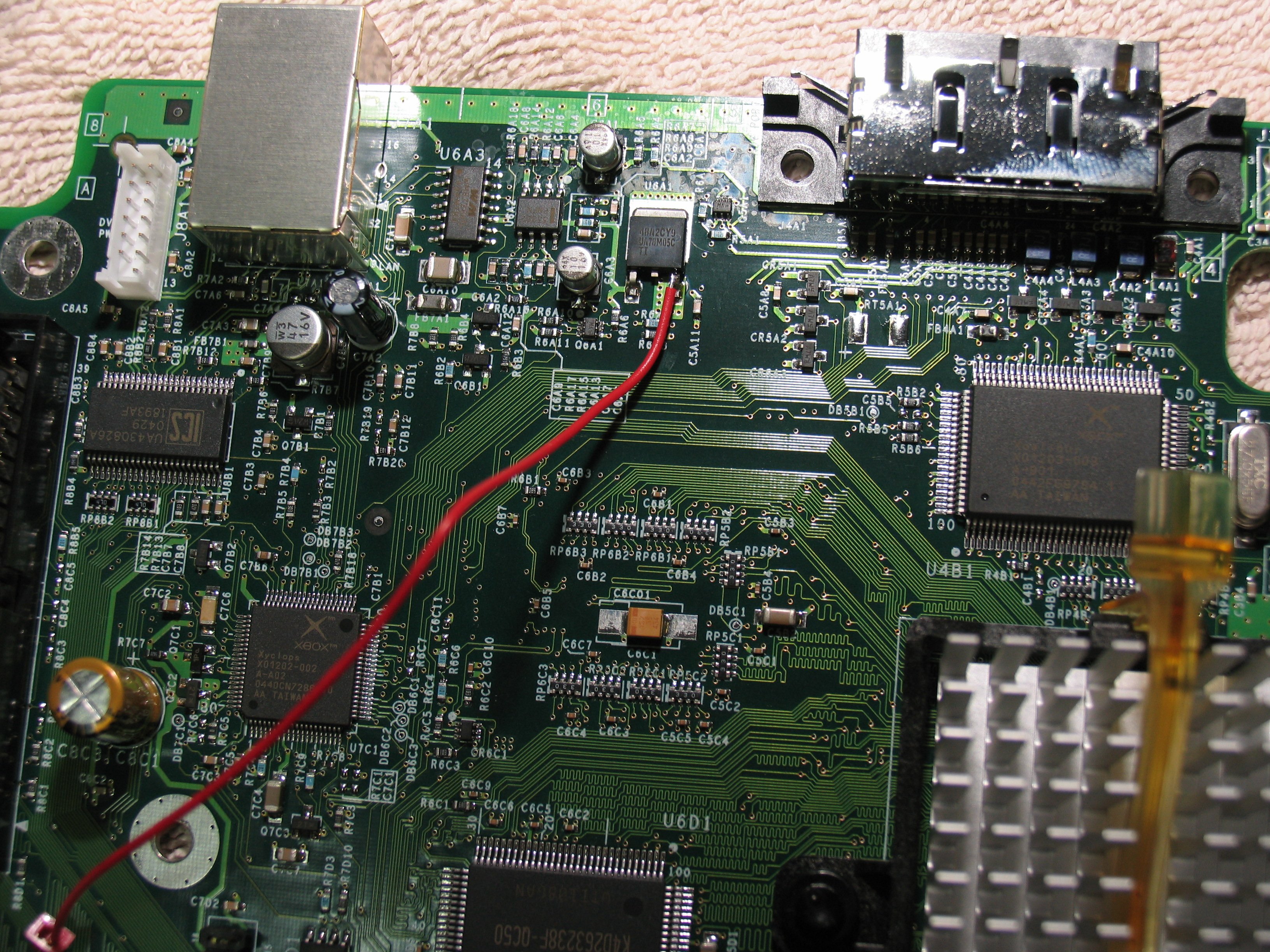
Mike's Xbox Repair
Not sure if this will work but I'm going to try. The xbox
just lost all video. Sounds work, lights work but just no
graphics which are kind of important to play it. Here is
my attempt at fixing it anyway.
First time for everything!!
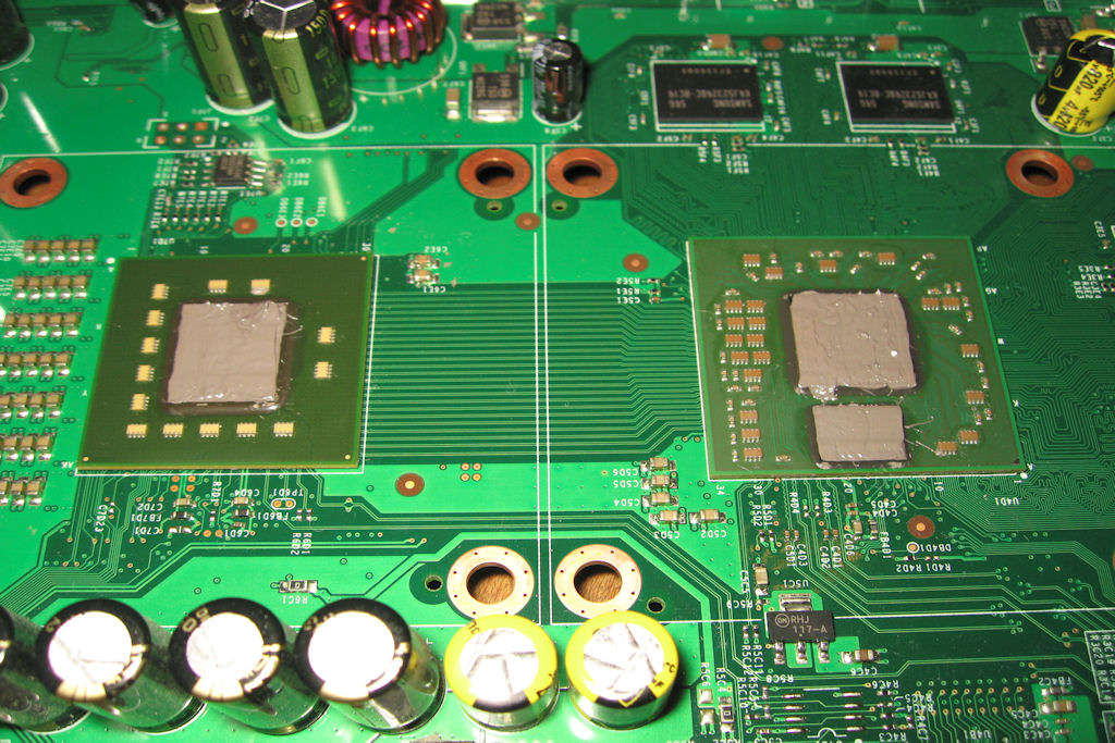
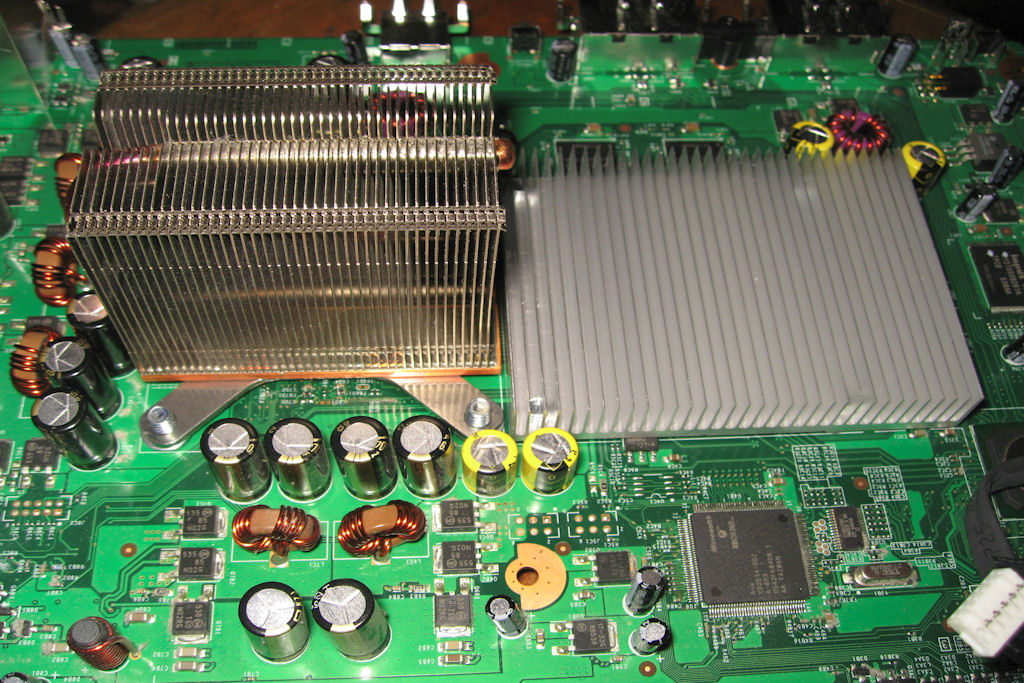
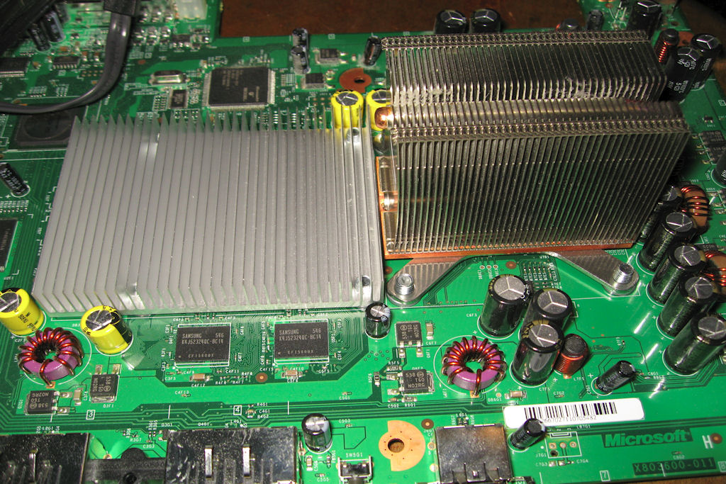
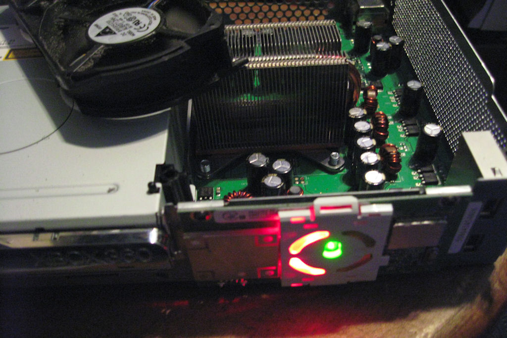
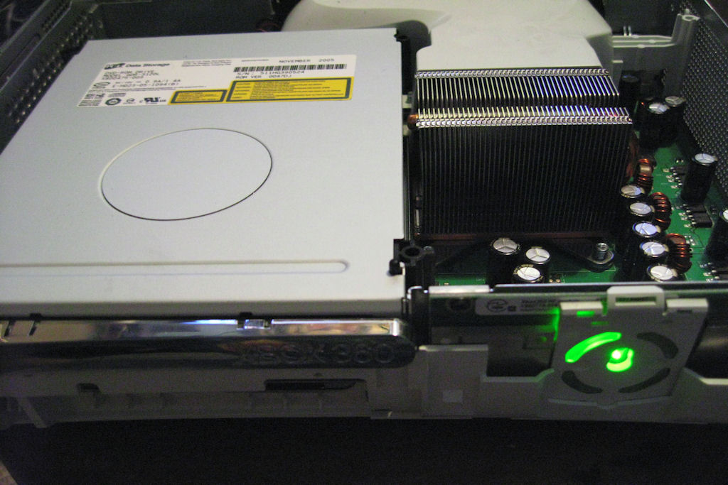
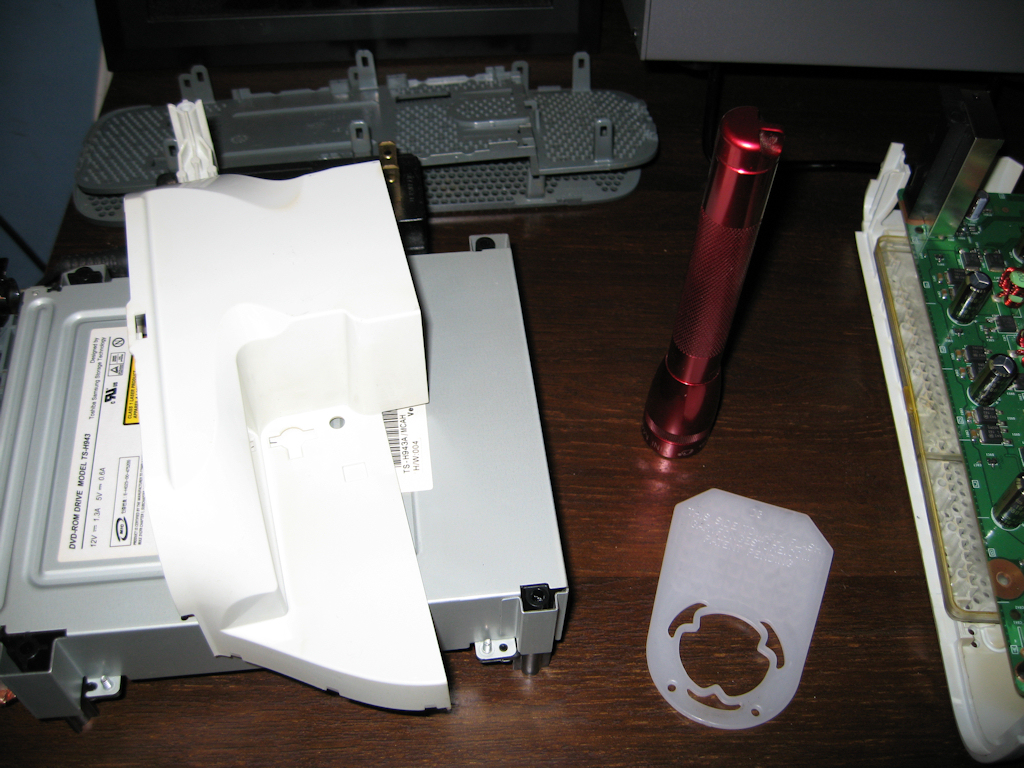
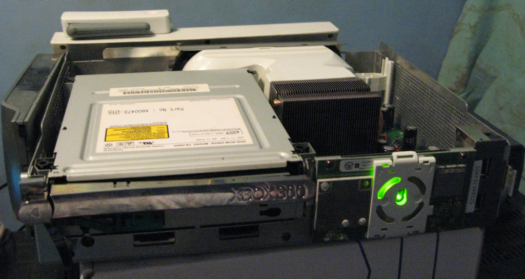
update:
01-09-10
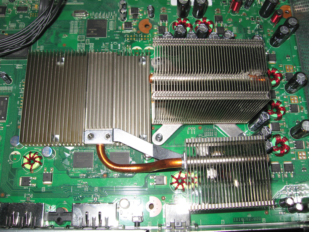
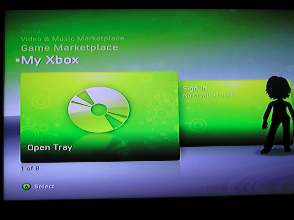
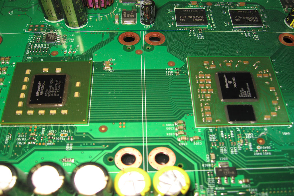
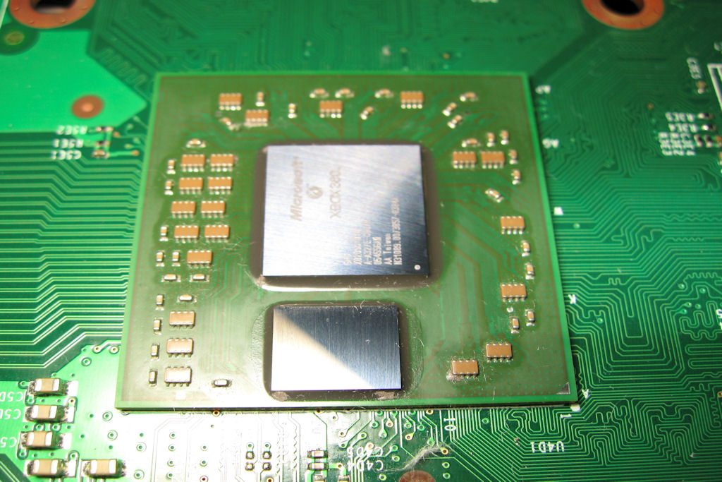
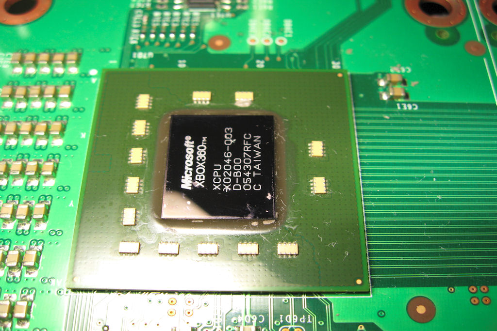
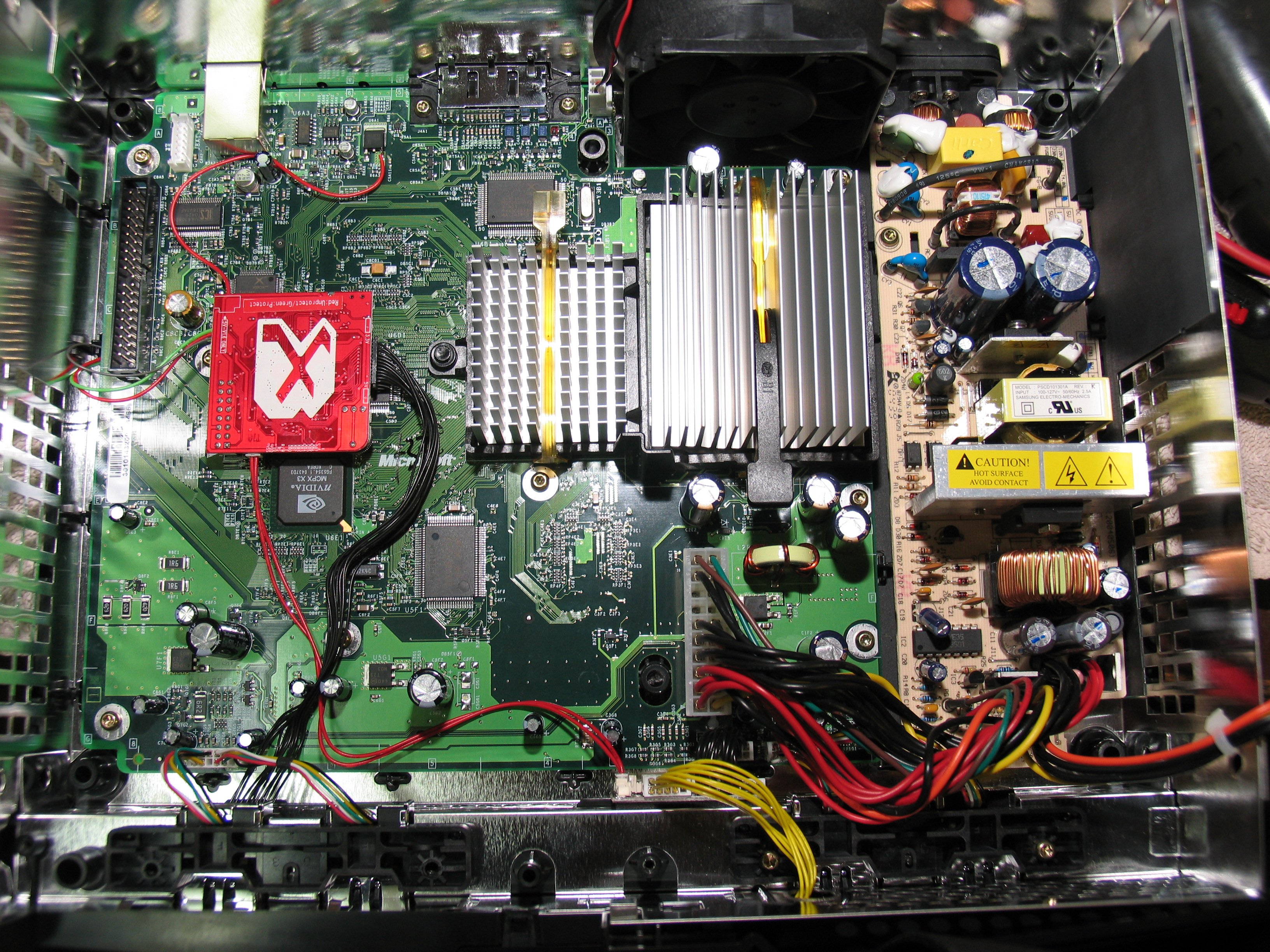
Well I did the fix and when I plugged it in it actually
worked fine. I still did the overheat trick just for good
measure. Here are pics of the newer style xbox.
![]()
12-20-09
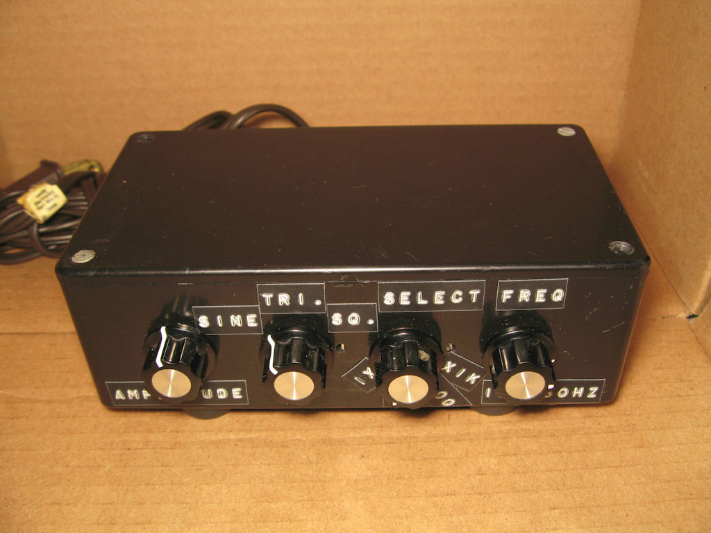
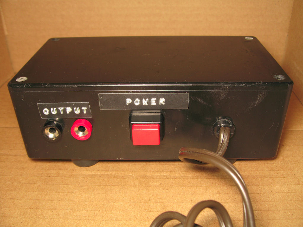
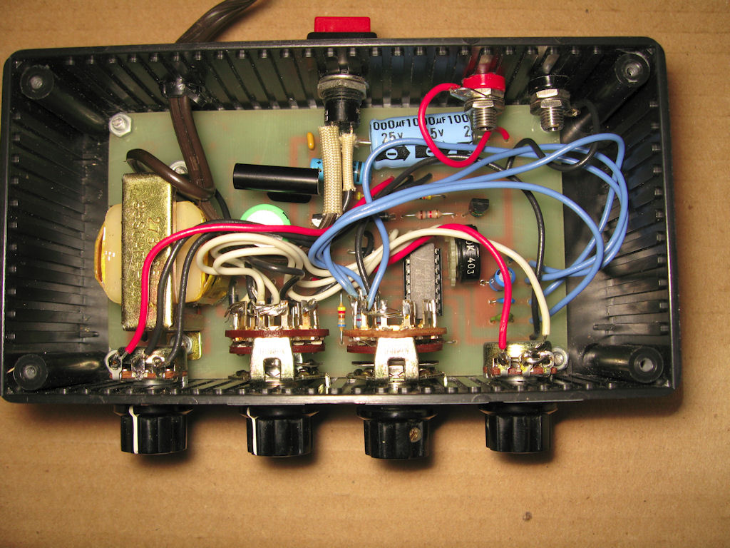
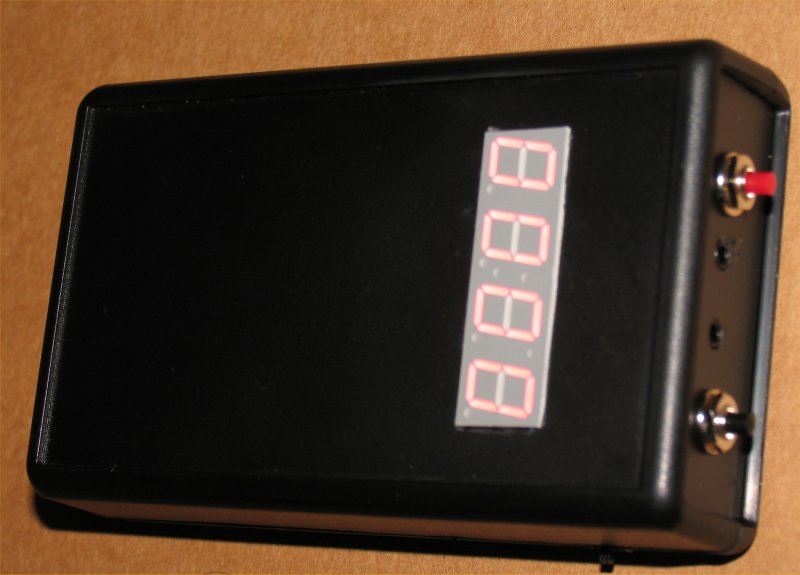
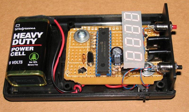
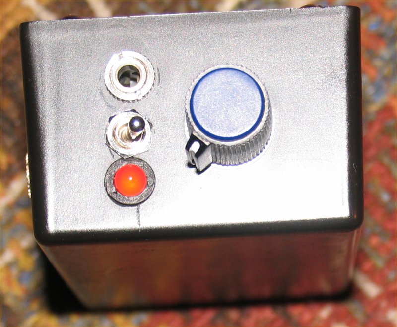
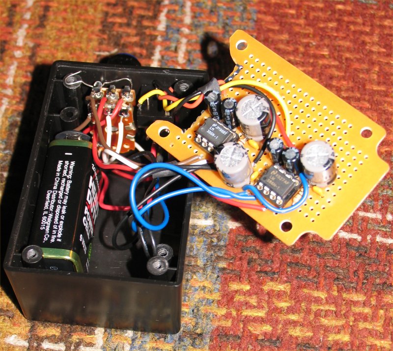
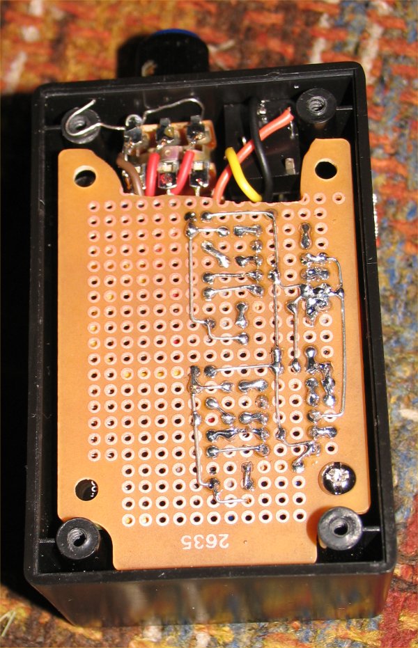
Function Generator
This is an old project. I built it in high school as my Electric
shop senior project or at least this was one of them. I was
given a schematic from which I had to design a pc board so
none of the wires crossed. I then had to make a drawing
twice the size of the actual board which I used a drafting
board I had at home to do it with. And since I was in
BW photography class my teacher helped me make a
positive film from my velum drawing. I then etched the
board, installed the components and the thing actually
worked! I then had to calibrate the waveform and here
is the result from all the work.
![]()
12-20-09
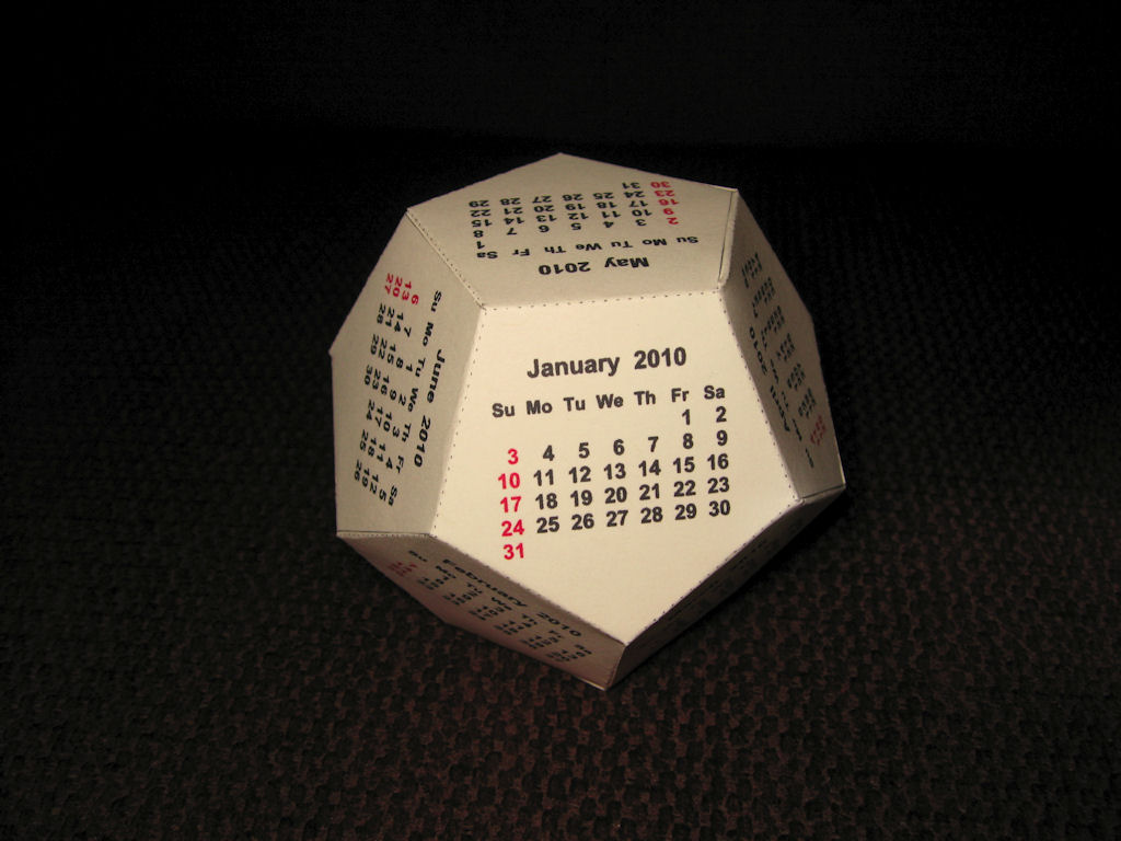
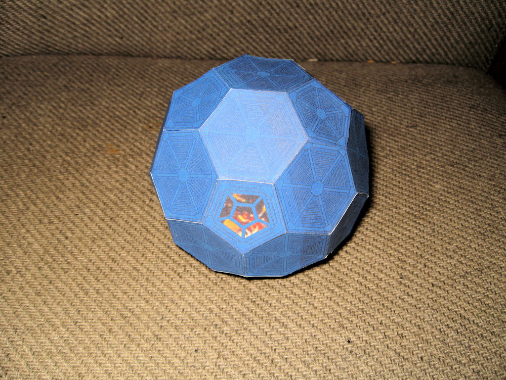
Year end Papercraft
I made a Christmas tree and a 2010 calendar to end
out the year for paper models or papercraft.
![]()
11-15-09
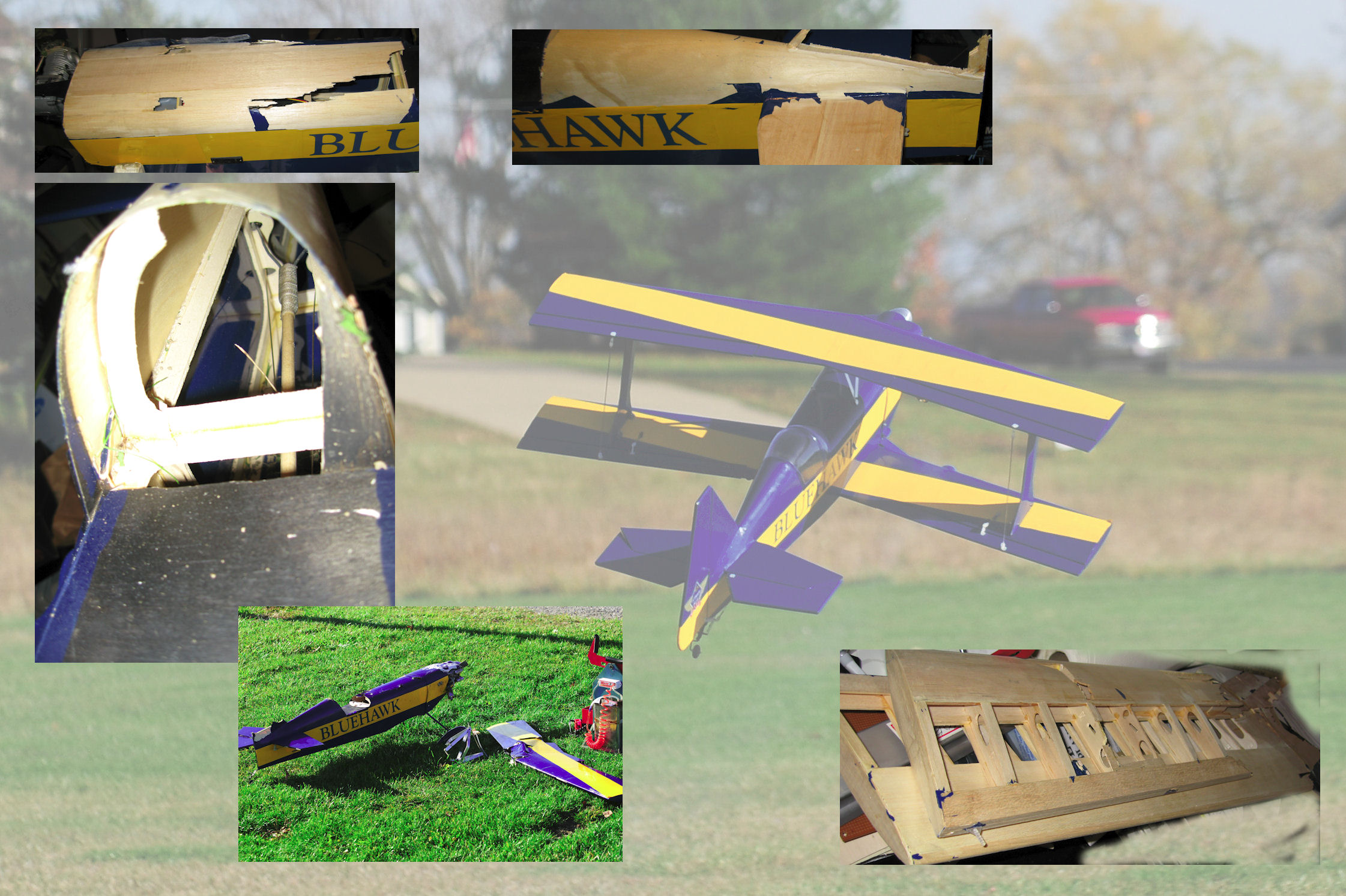
Biplane Repairs
Well it was going to happen sooner or later but I
guess sooner was the one for me. After a gust of wind
slammed my plane into the ground I now have to repair
my biplane and here will be the updates.
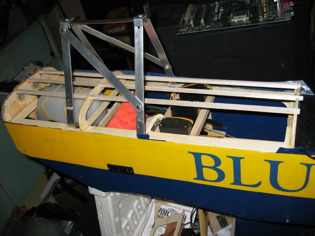
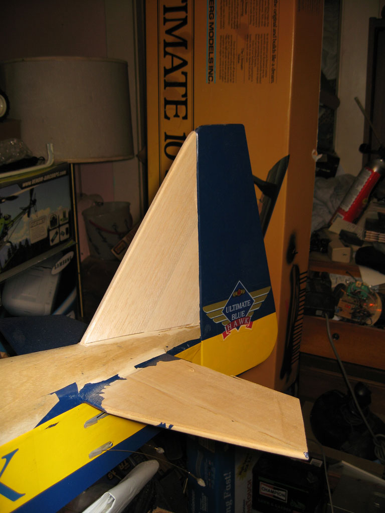
11-21-09
Biplane Rudder Repairs
I got the rudder or tail fin pretty much done. I also have
a pic of the start of the fuselage repair.
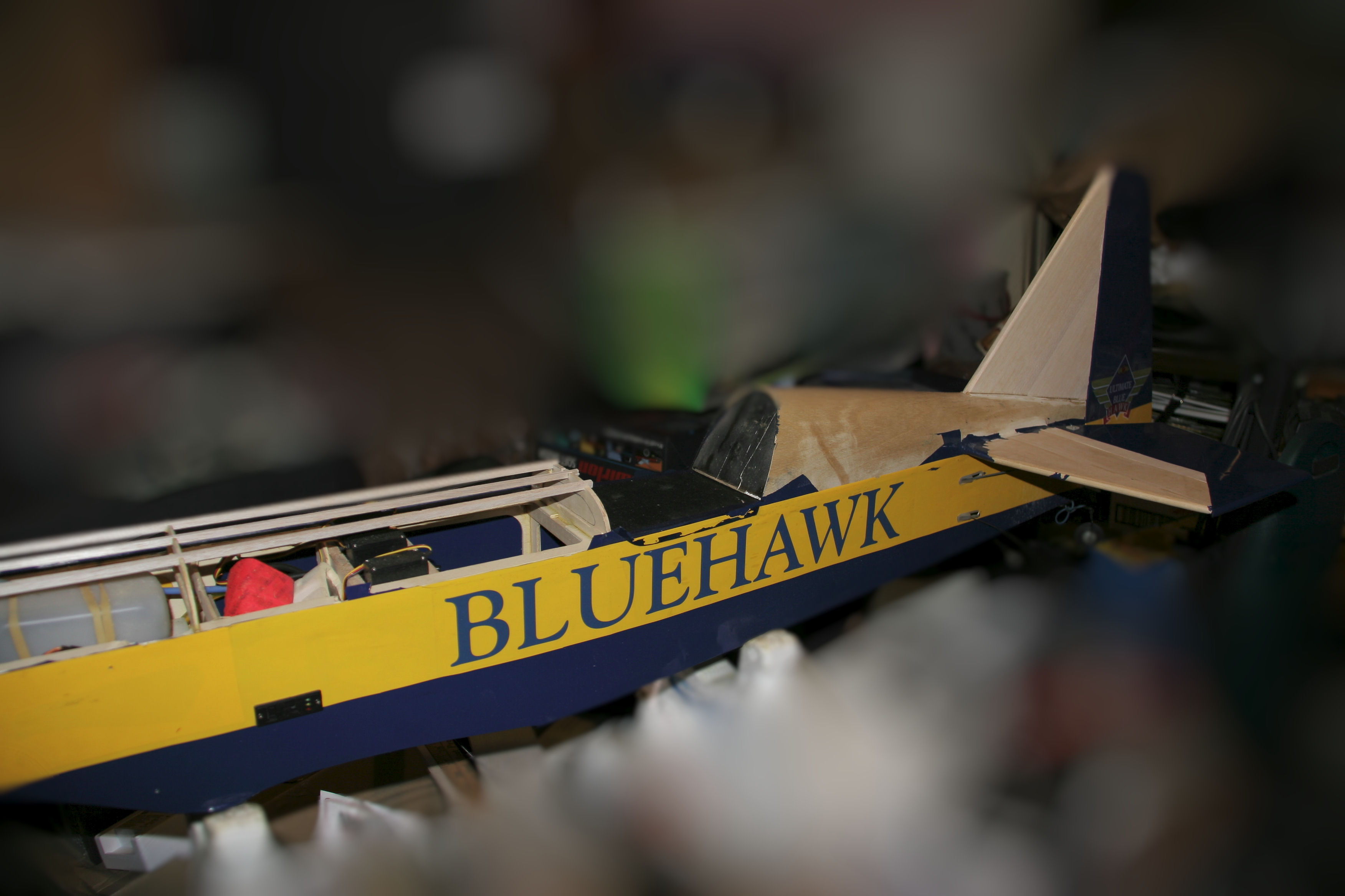
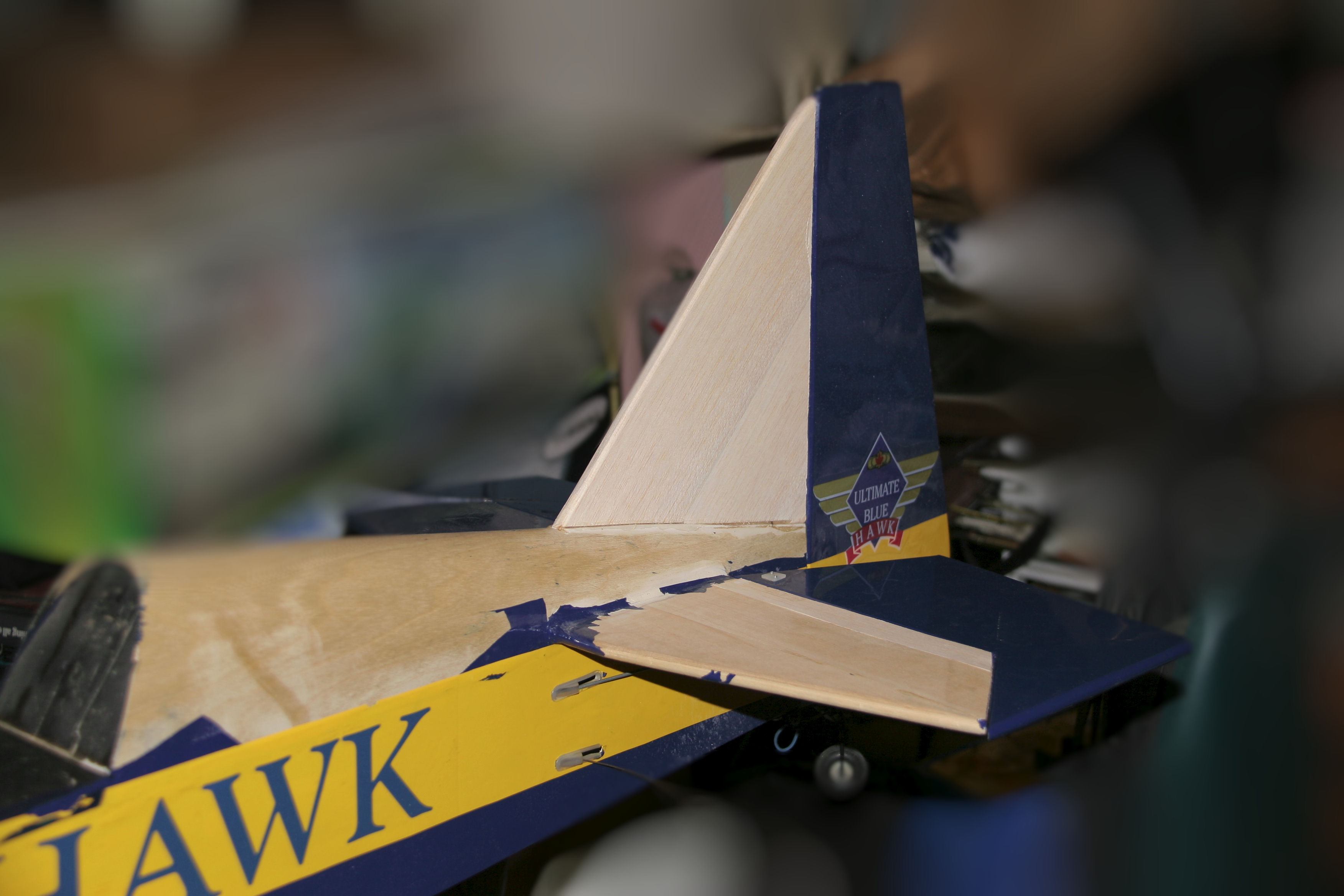
11-22-09
Biplane HStab Repairs
I got the horizontal stabilizer repaired so the tail
section is about done now.
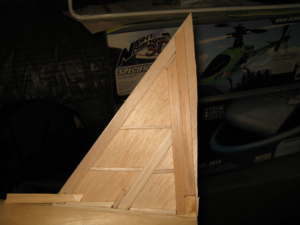
11-27-09
Biplane Wing Strut Repairs
I started the cutout process for making the
wing supports out of plywood.
12-24-09
Wing Struts
I cut out plywood doublers to support
the bottom wing strut mounts and
all I got to do is make up some epoxy
and start gluing stuff.
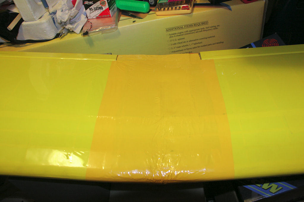
12-26-09
Biplane Wing Strut Repairs
I got the wing struts cut out, sanded and
built up. All I need to do now is taper the
balsa and cover them and that will be one
repair out of the way.
![]()
11-13-09
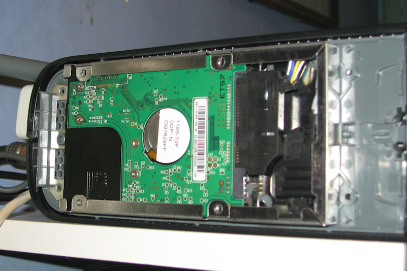
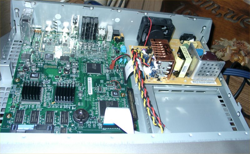
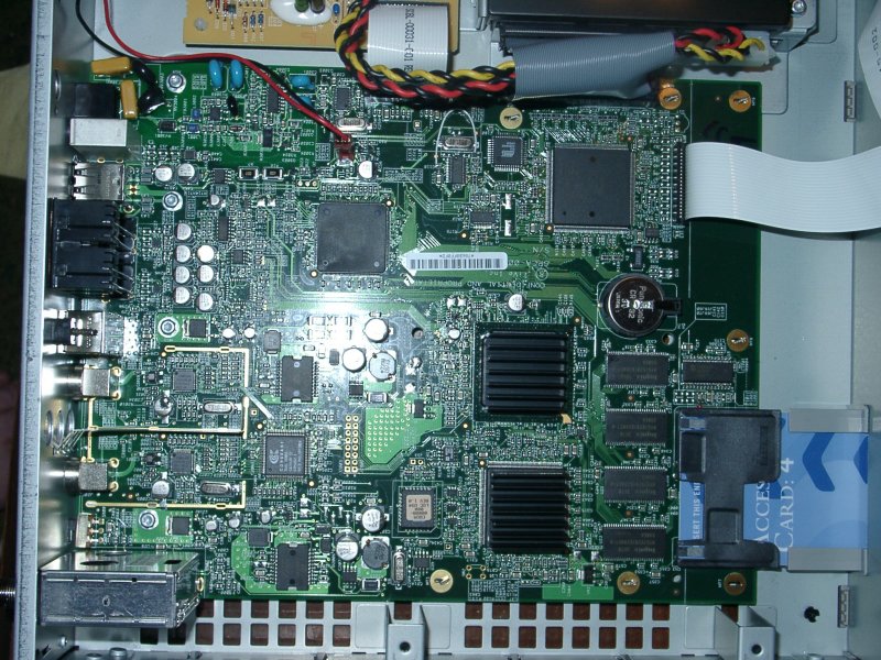
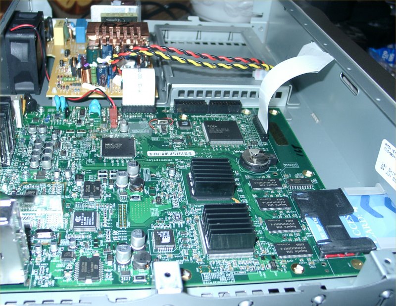
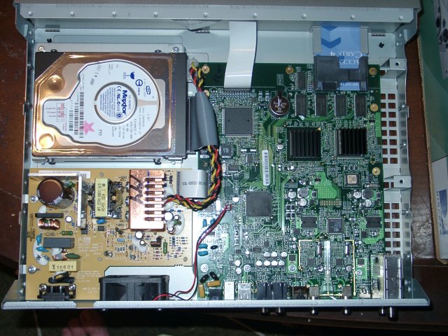
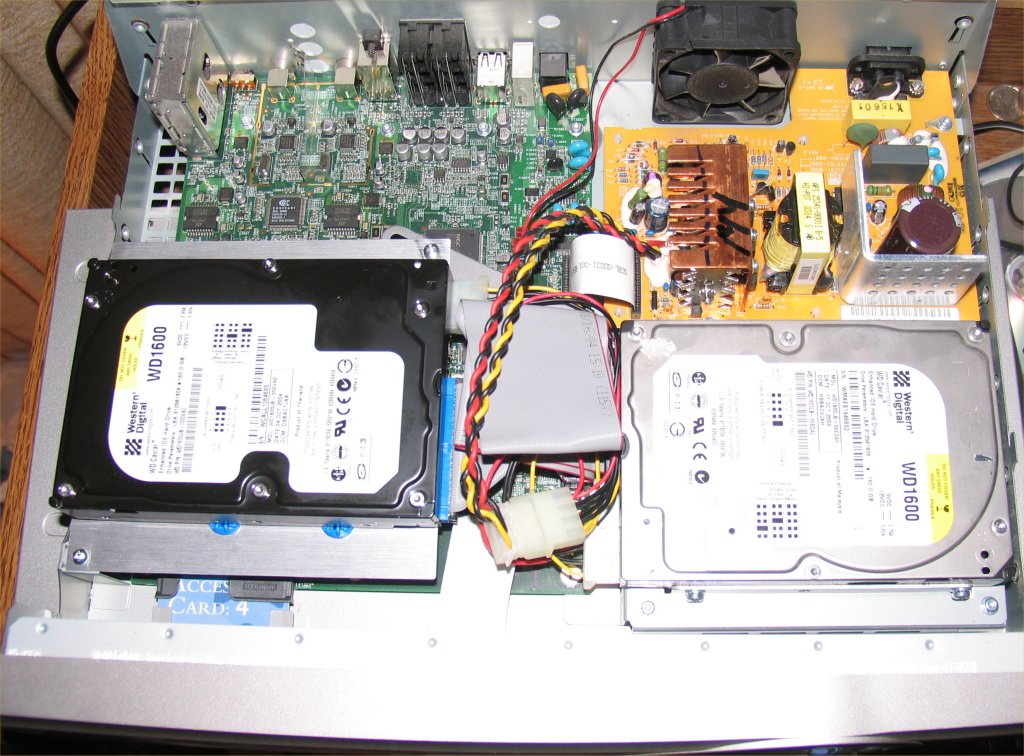
Xbox 360 HDD 250gb upgrade
I upgraded my programs hard drive and had a spare
250gb drive available to see if I could upgrade my old
20gb xbox drive to a new 250gb size like my new CoD
xbox unit that came with a 250gb drive. After lots of
work I got it to work, installed a game on it and it
actually played. So now my old xbox is able to have
a 250gb drive like my new xbox does!!!! yeah!!
I just can't get on xbox live using it...Sounds like Sony
has their head in the game. They let you install new
drives in their boxes without any problems so why not
Micro$oft?
![]()
10-24-09
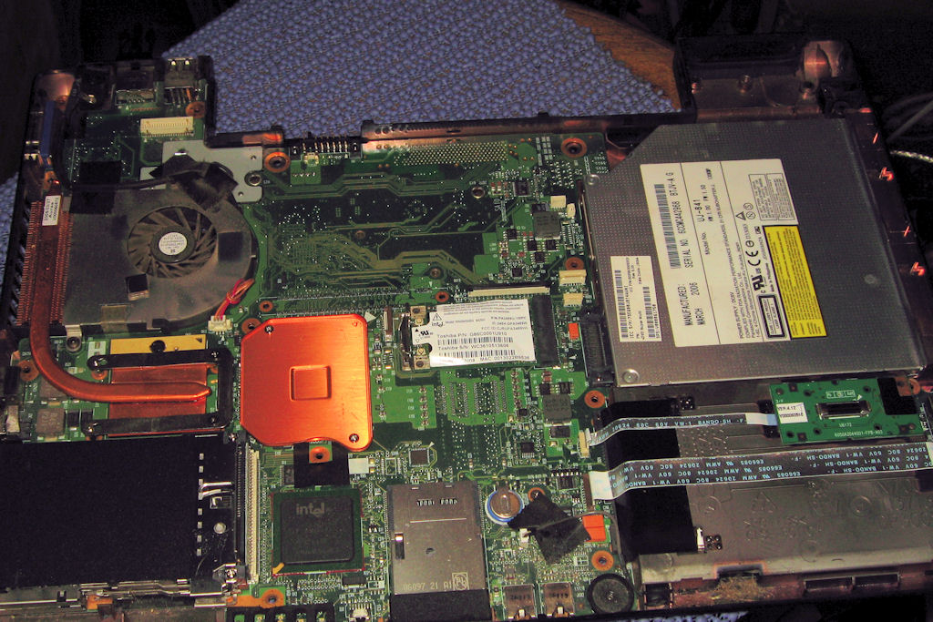
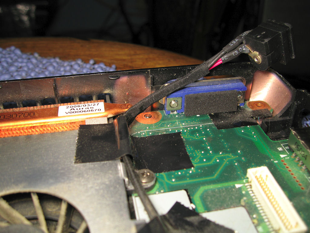
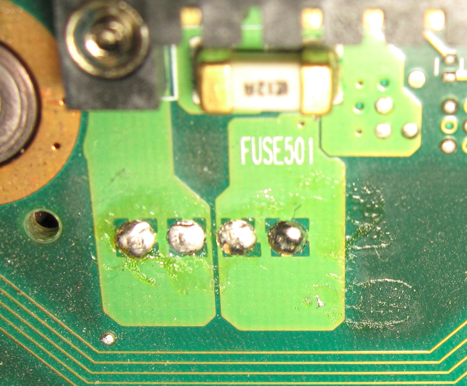
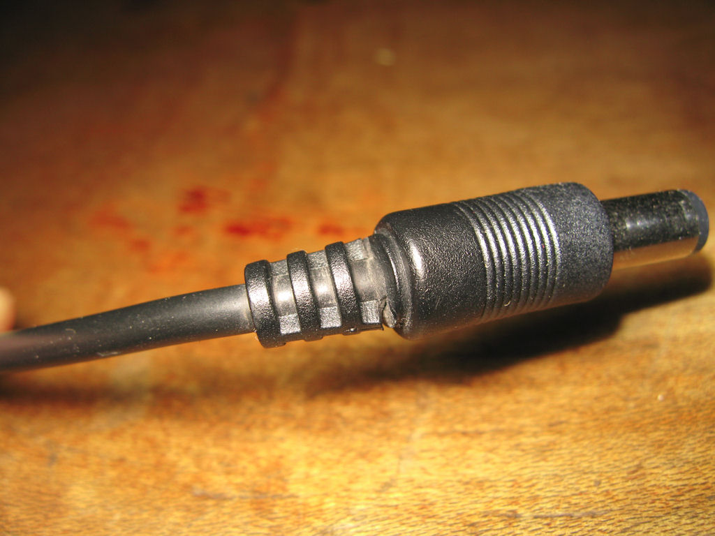
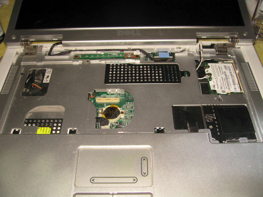
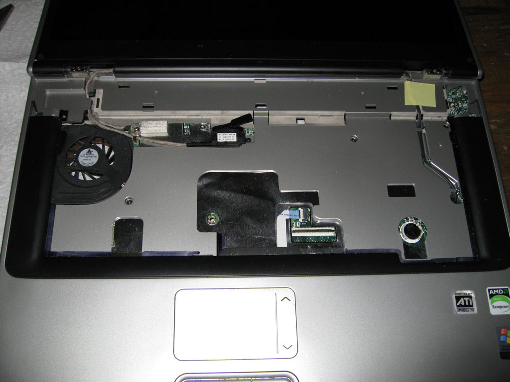
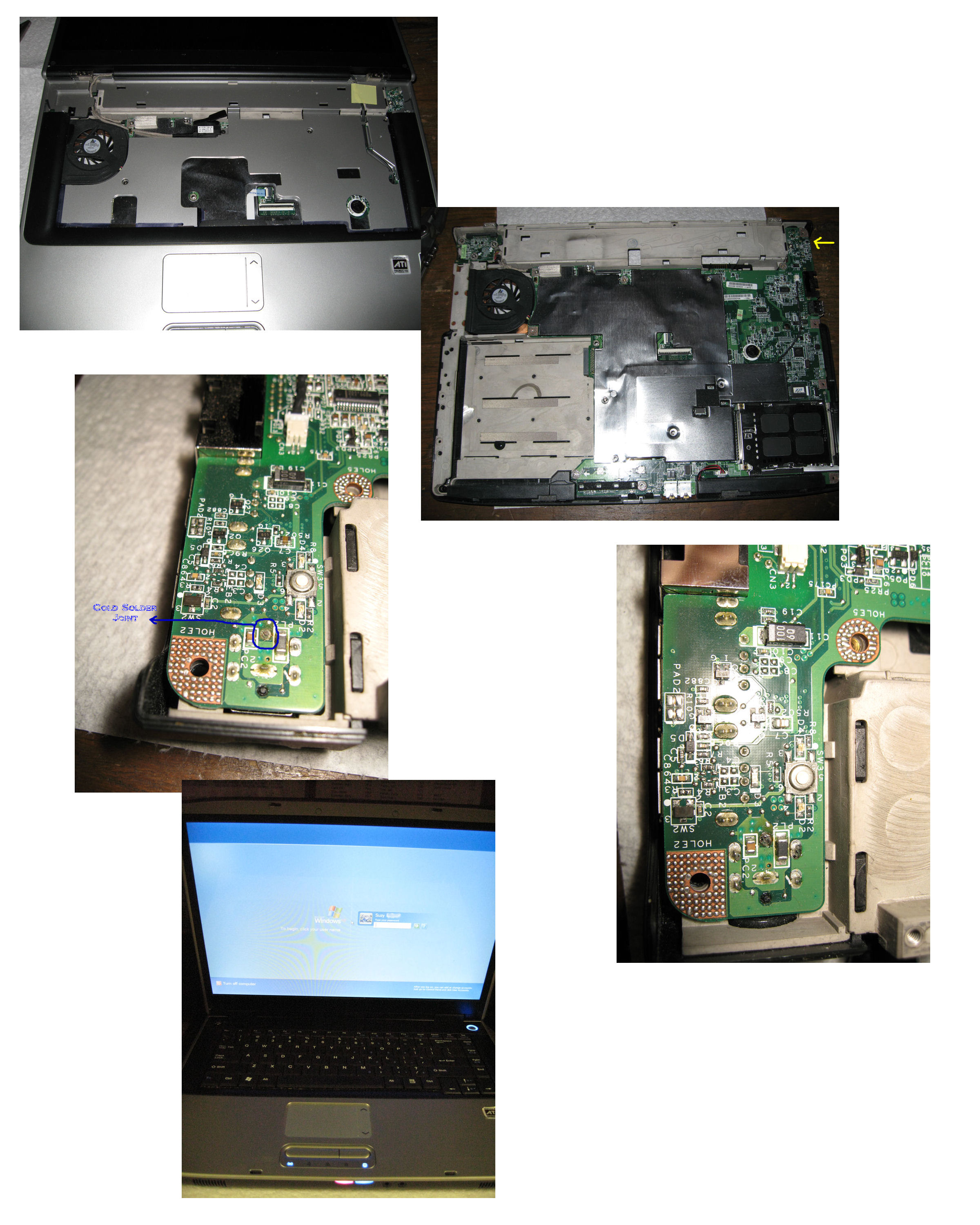
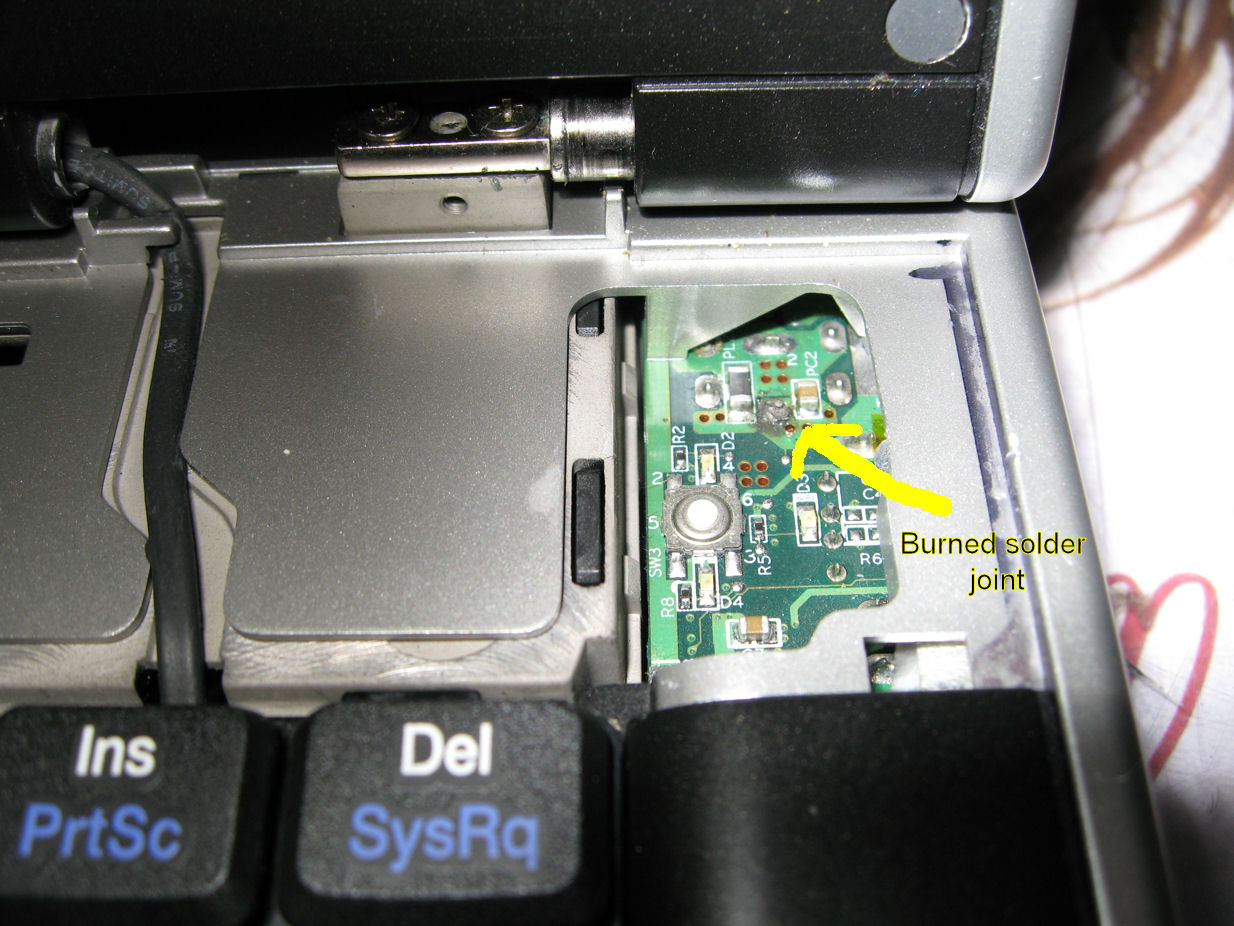
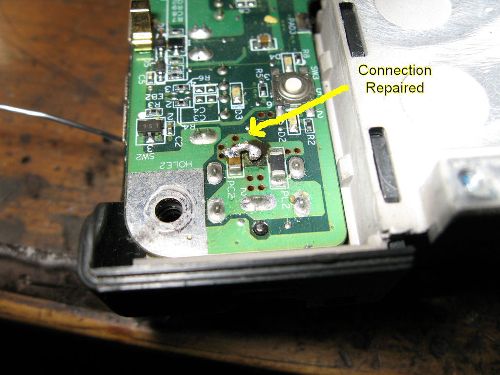
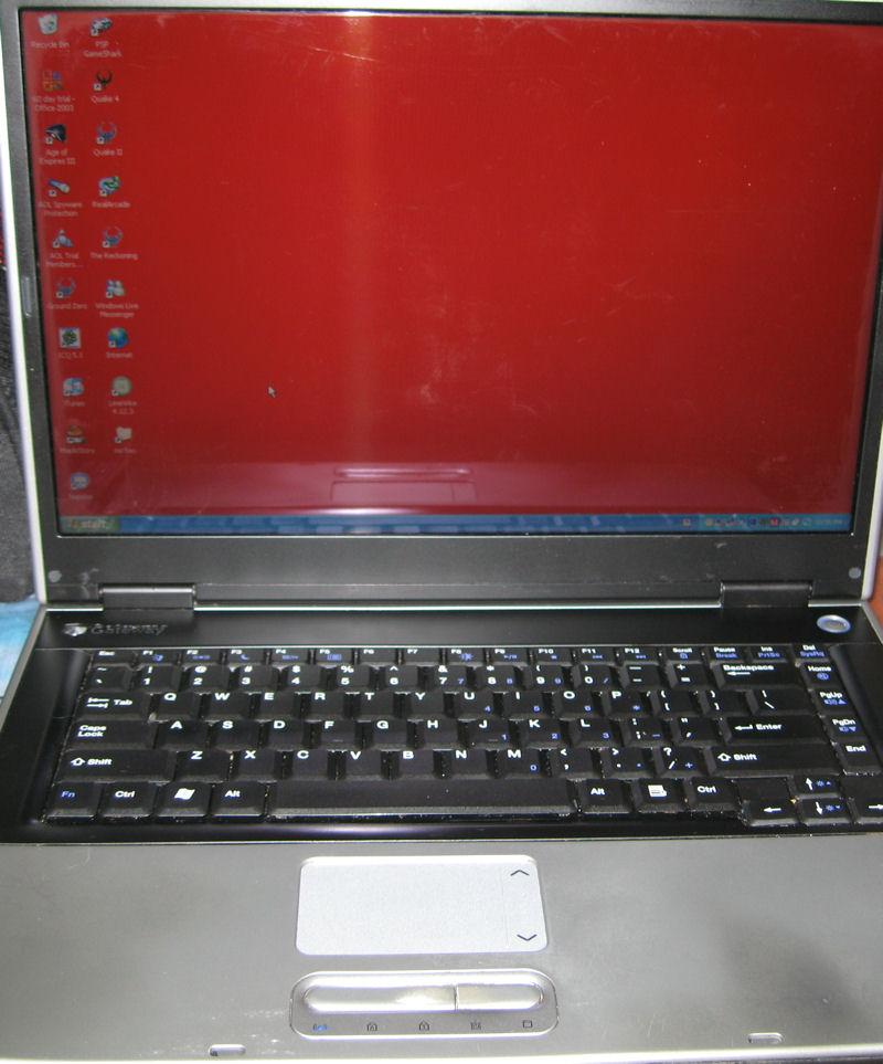
Toshiba Laptop repair
I got yet another laptop for repair as the battery wont
charge or have the pc come on. I checked the connection
and found the plug floating around like all the others but after
ripping the laptop apart I found that toshiba doesn't solder
the plug to the motherboard but instead they have a separate
wire and plug that mounts to the case. I got a new respect
for Toshibas now. So the MB wasn't the problem as I found
out so I checked the plug to find it was at fault. It looked
like the plug was unplugged a few times by pulling on the
wire instead of grabbing the plug to unplug it. I cut all the
plastic off the plug, cut back the wire where it was broke
and soldered the wires back on. Now I got to figure out
a way to insulate it and strengthen it or the owner will
need to buy a new power supply or just a new plug if
they are available.
![]()
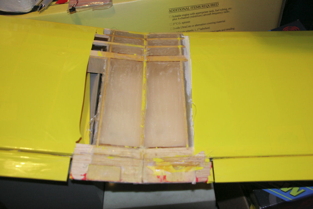
9-30-09
Biplane Repair
After flying this summer I was putting my plane together
to hang up and noticed the wing mount was loose so after
investigating it I found the fuse was cracked inside so here
is the reinforcement repair I did.
![]()
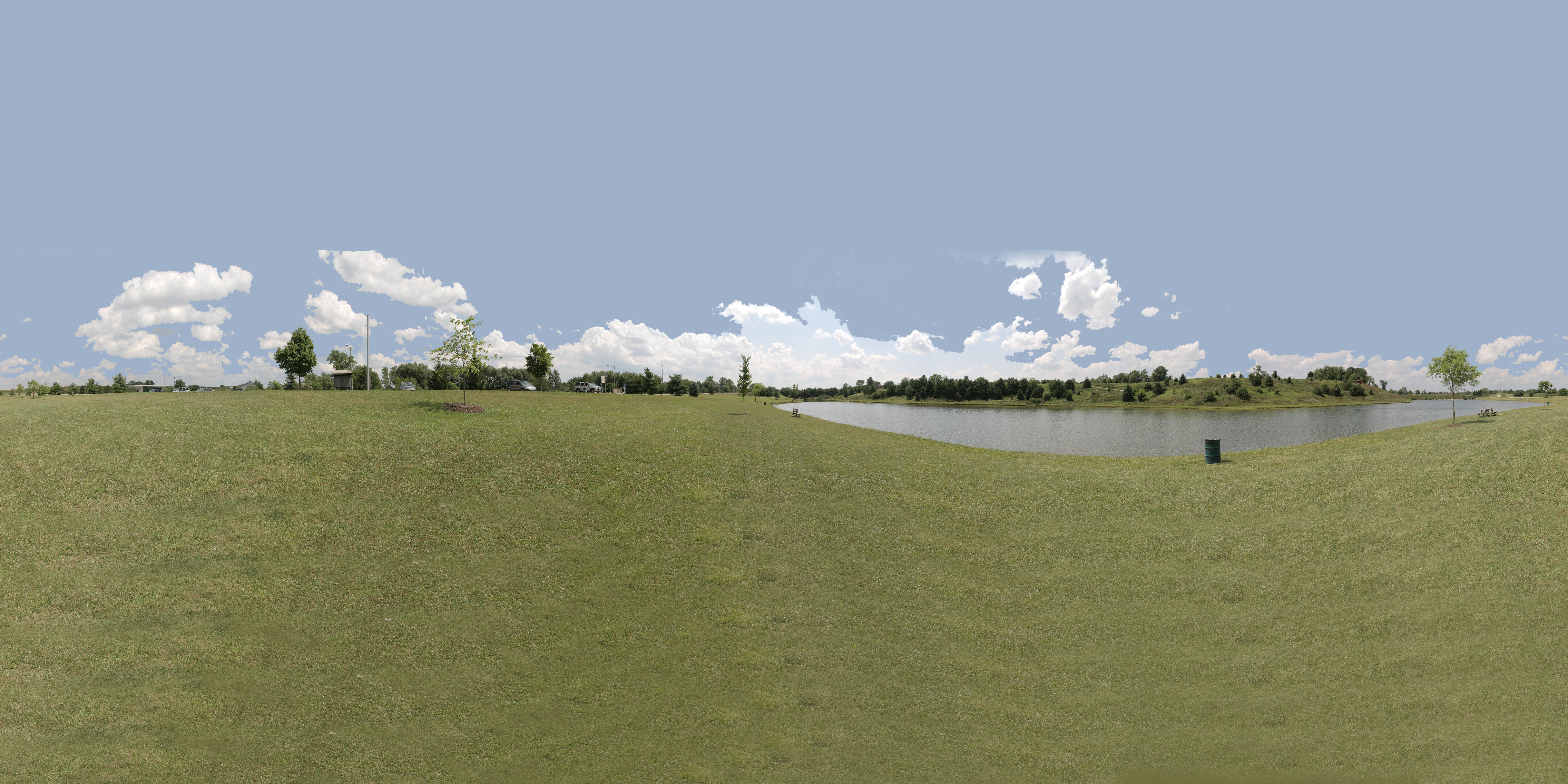
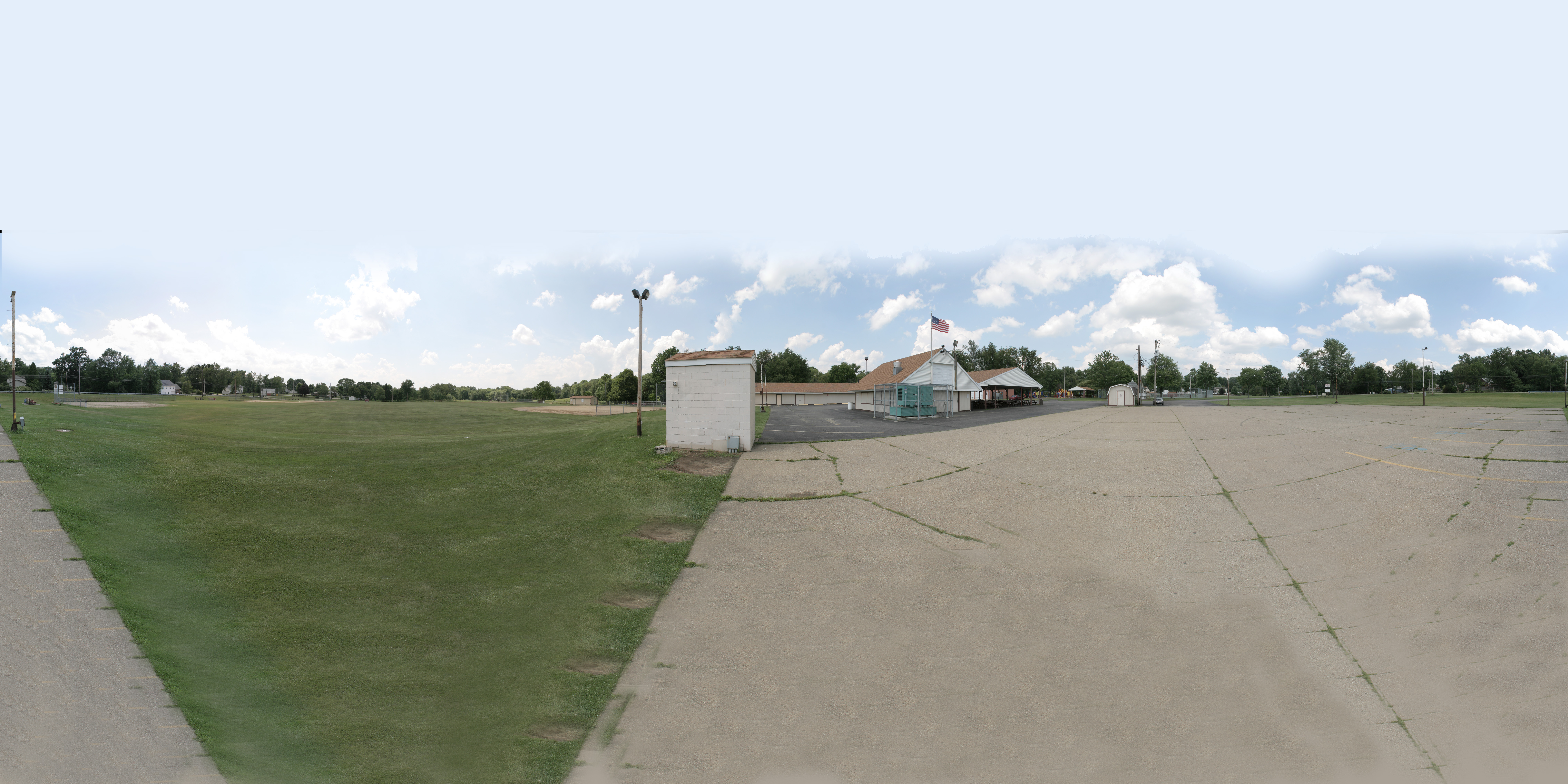
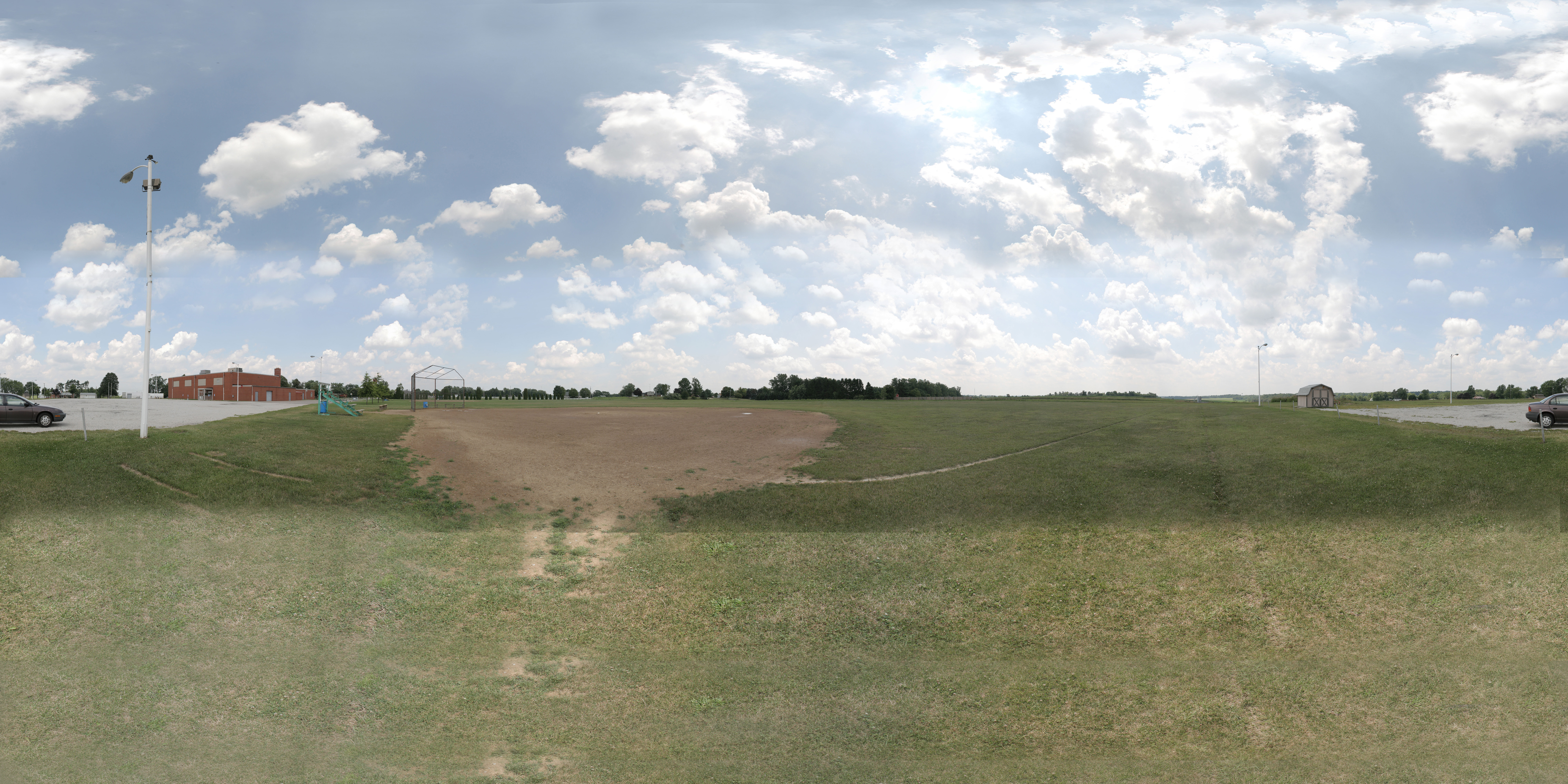
9-30-09
More Realflight Photo Fields
I've been playing around with my panoramic head
for my camera and here are some test shots that I
used for my RealFlight program. Just import them as
a photo field and you can fly there.
Hand held:
Here is a Virtual Flying field of
Sacred Heart of Mary where I fly.
If you can't see the field, try another
browser or update your programs
This file needs quicktime to run
properly.
I Imported my 360x180 image for realflight
into gocubic program to produce the mov
file for this.
![]()
9-17-09
Trainer Being Revived
I have a PT-40 trainer that was wrecked and I got
it repaired and now covered and all the controls
installed so it is ready to fly again after 10-12 years?
Here are a couple pics of the repair work.
![]()
8-24-09
Another Xbox Bites the Dust
This time the xbox is mine! So gutting the box
it must be. I got it fixed and played for 4 hours
without a problem. Pics to follow
![]()
8-21-09
Cindy Laptop Repair
Got another laptop for repair and this time it is more
HDD and fan problems then bad solder joints.
![]()
7-17-09
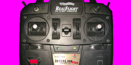
Realflight Esky Controller
Here is a controller setup for realflight for use
with the esky controller
![]()
7-11-09
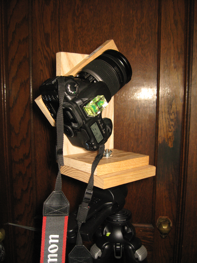
Panoramic Head
I found info on the internet for making your own pano head
so I thought I'd give it a try so I can make more photo fields
of places I may want to fly at.
![]()
7-9-09
Realflight Biplane Colors
Here are the files for the colorscheme I use for my
biplane for realflight 3.5
![]()
7-9-09
Realflight photofield
Here is a quick pic of the Sacred Heart of Mary's field
where I've always flown my plane. Just import it into
the realflight to fly where I'm used to flying
![]()
7-2-09
Realflight Xpadder Profile
I'm on the xpadder bug finding team and after working
with it today I got my controller for my realflight program
setup with xpadder and here are the files.
![]()
6-22-09
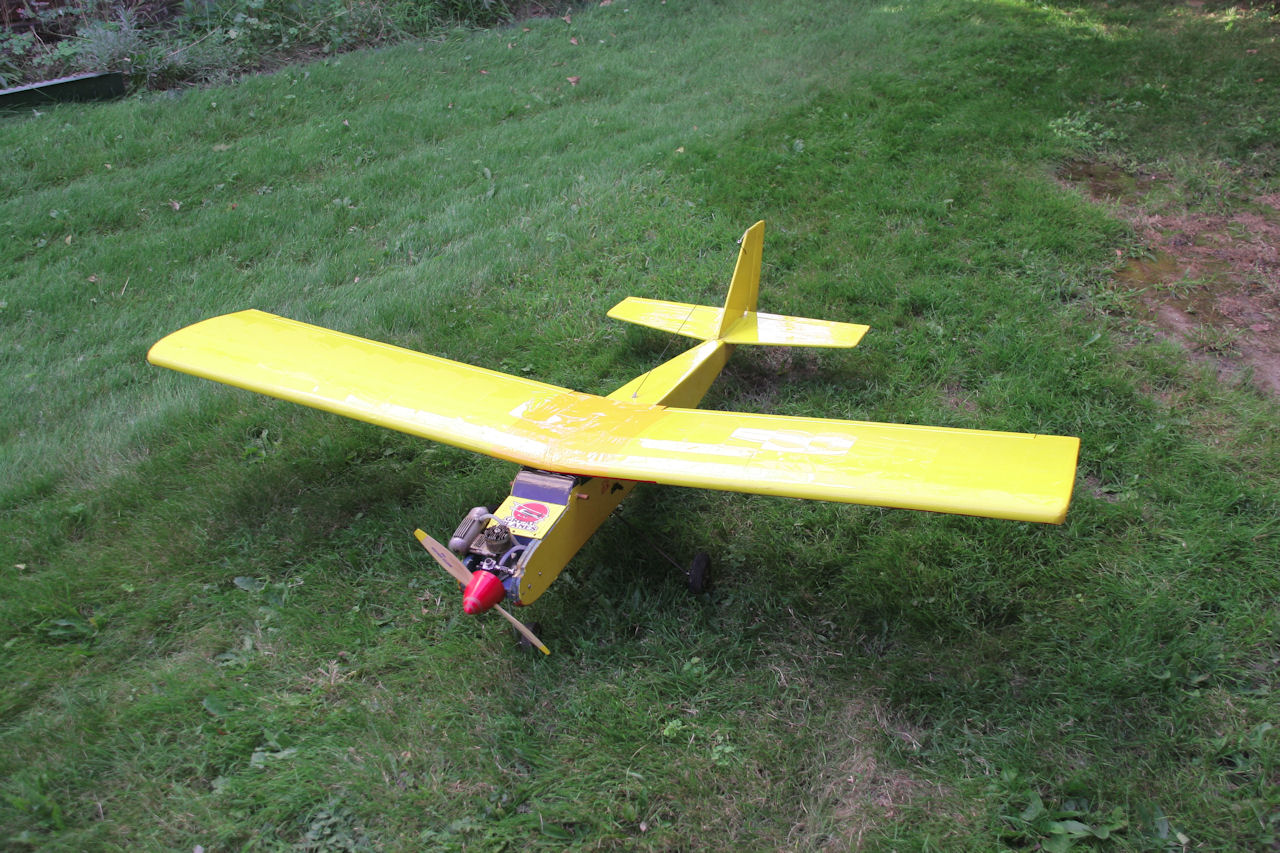
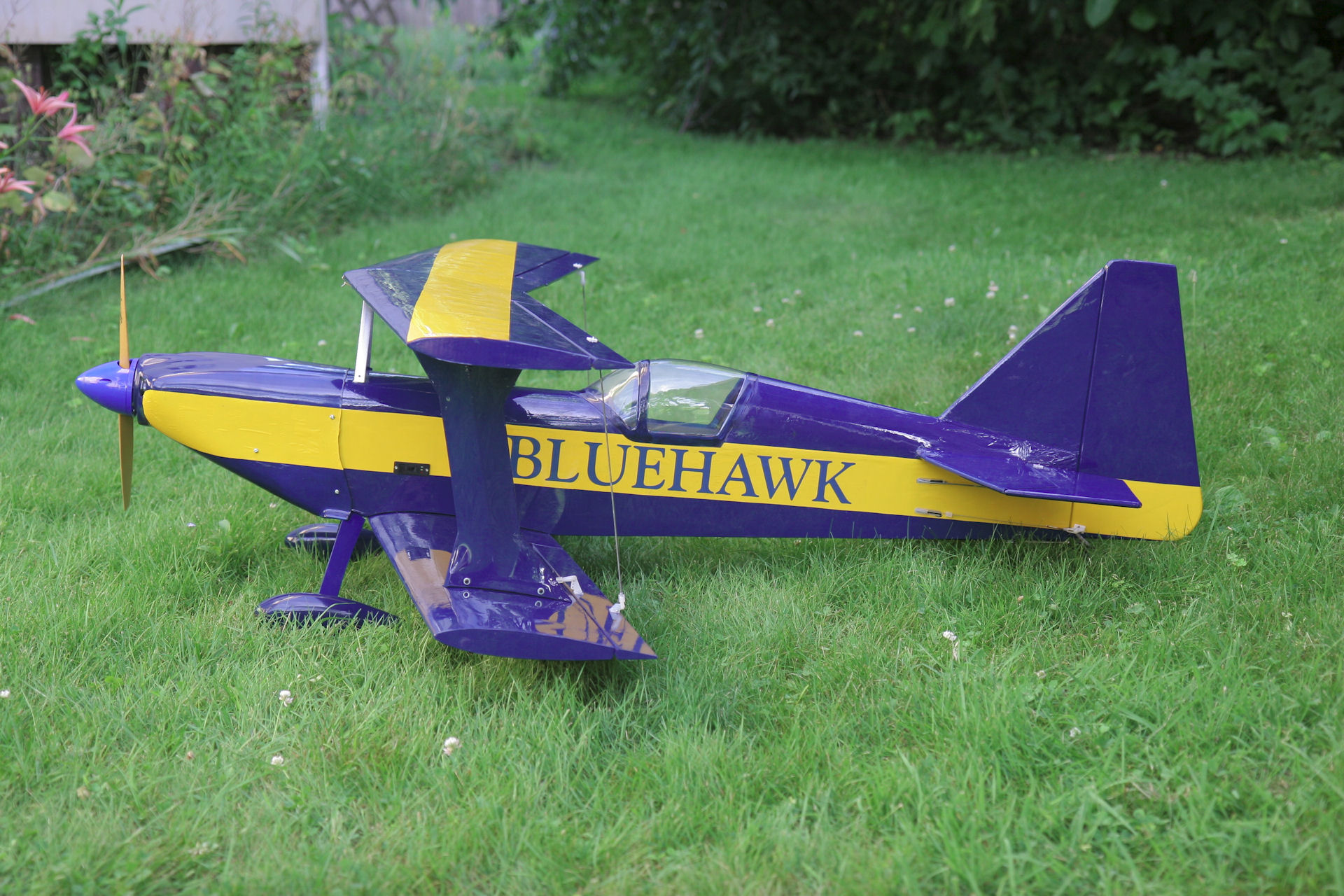
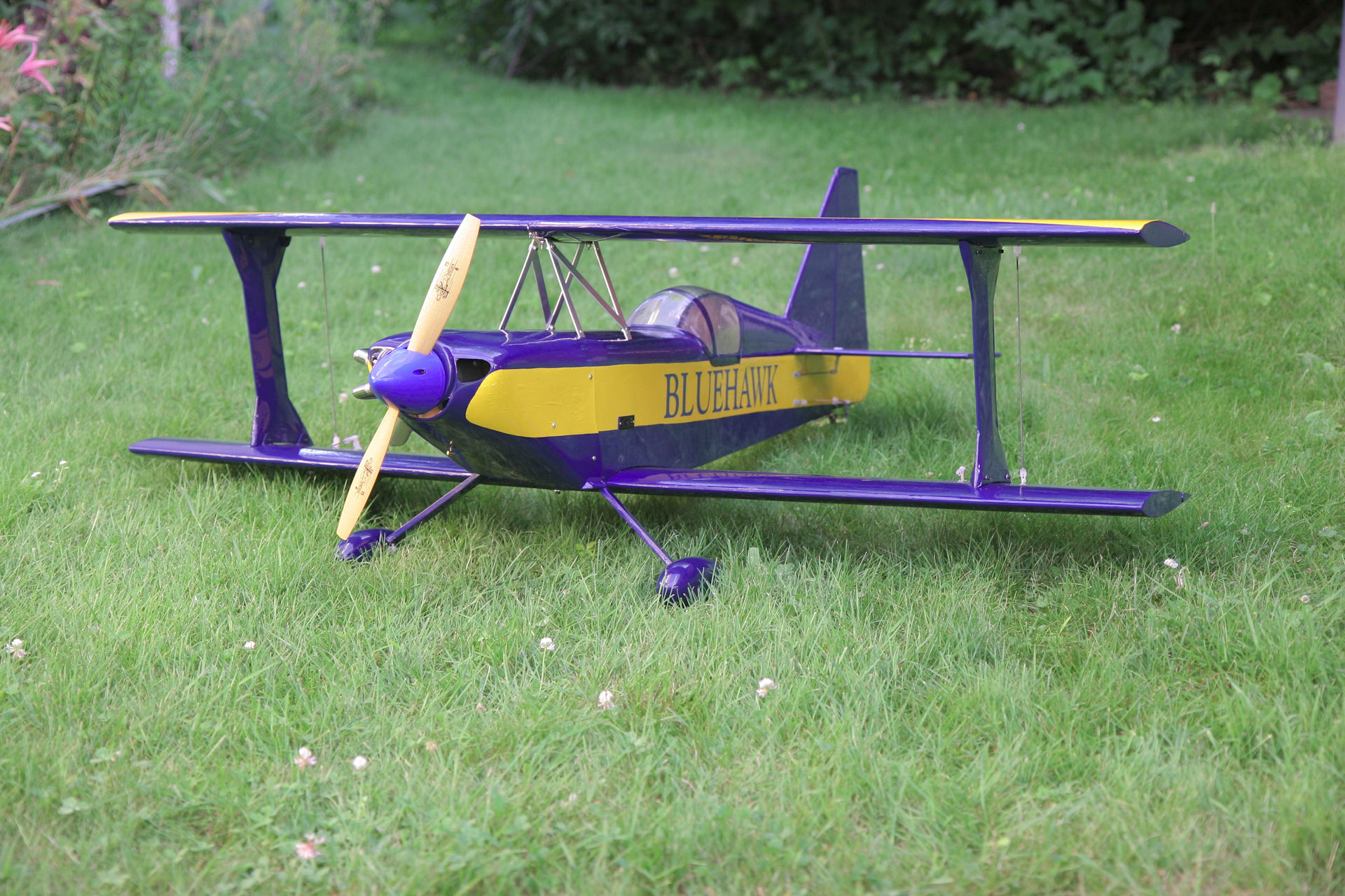
My Ultimate Biplane
Eleven years ago I started work on my biplane and had to
quit. I then lost interest as I had several other planes at
the time and this year I decided to finish it so here are
some pics for you.
update:
6-28-09
I started my engine for the first time in 11 years after I bought
it. It started right up and I ran it for 40 minutes to break it
in. I got some finishing touches to do and off to the flying
field I go.
update:
7-2-09
I balanced my plane by adding 8oz to the tail section.
I had to ditch the idea of smoke for now as the motor
interferes with the radio too much for me to feel
safe to fly it.
update:
7-09-09
My biplane had its maiden flight today with no major
problems. At least it came down in one piece. I did
have several problems. The engine shook its screws
loose which have been replaced with socket head bolts.
The wing struts were missing 4 of the 8 bolts which now
has locktite and a locking nut on the back of them. The
screw from the throttle servo fell out but the contol arm
stayed on thankfully. And lastly the fuselage was broke
loose at two of the joints from the wings vibrating around.
I still need to glue them but it is still able to have another
flight.
Thanks to Ron and Jim for taking Pictures and videos
for me of my first flight with the biplane!!!!
![]()
4-11-09
My Nephew's buddy Xbox360 repair
Well I got my third xbox 360 repaired from the usual
red ring of death problem that haunts xbox 360 owners.
I did the usual xclamp replacement and reinstalled to
get it to work again and then over heated it to get the
connections to make again.
![]()
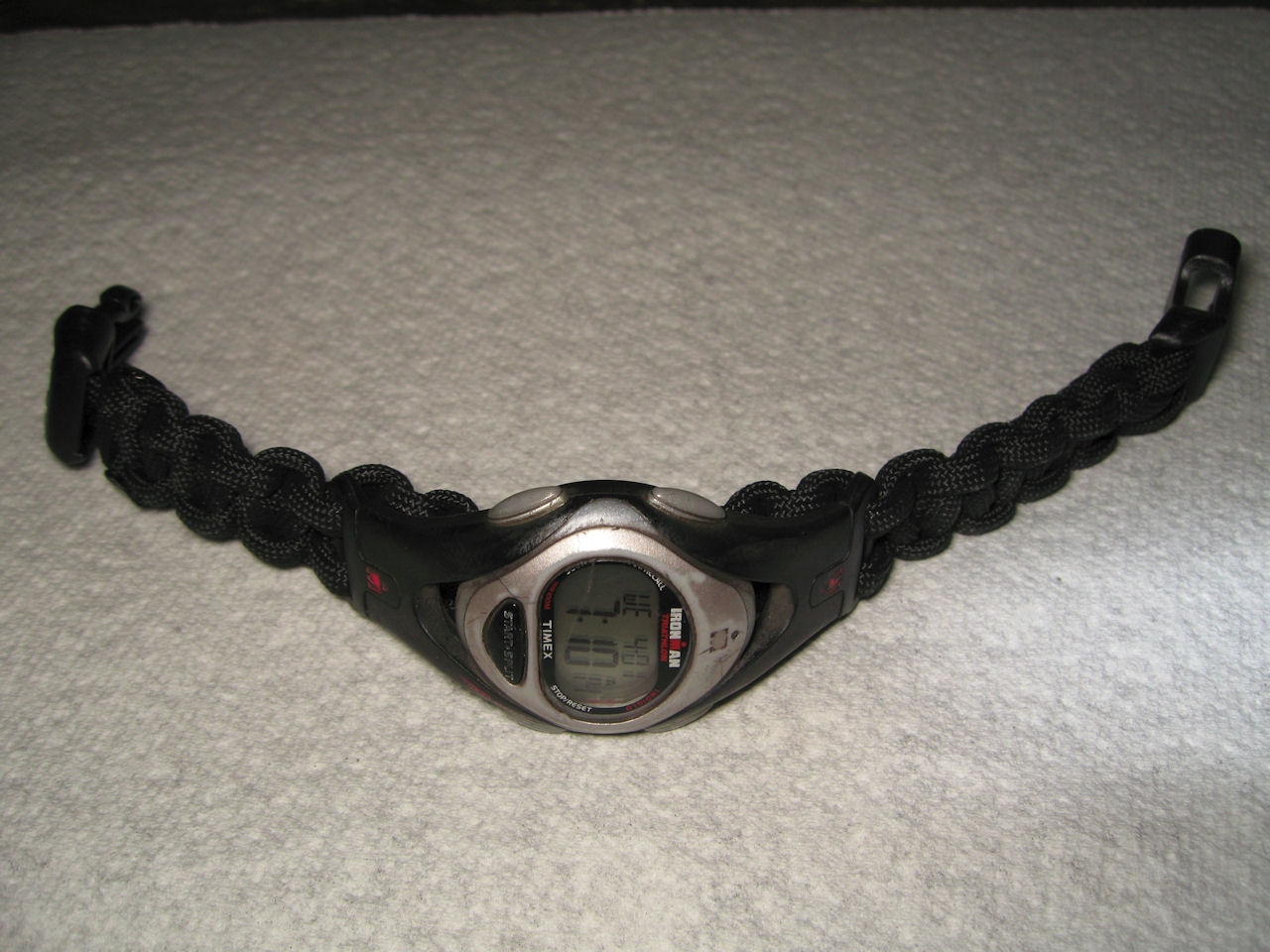
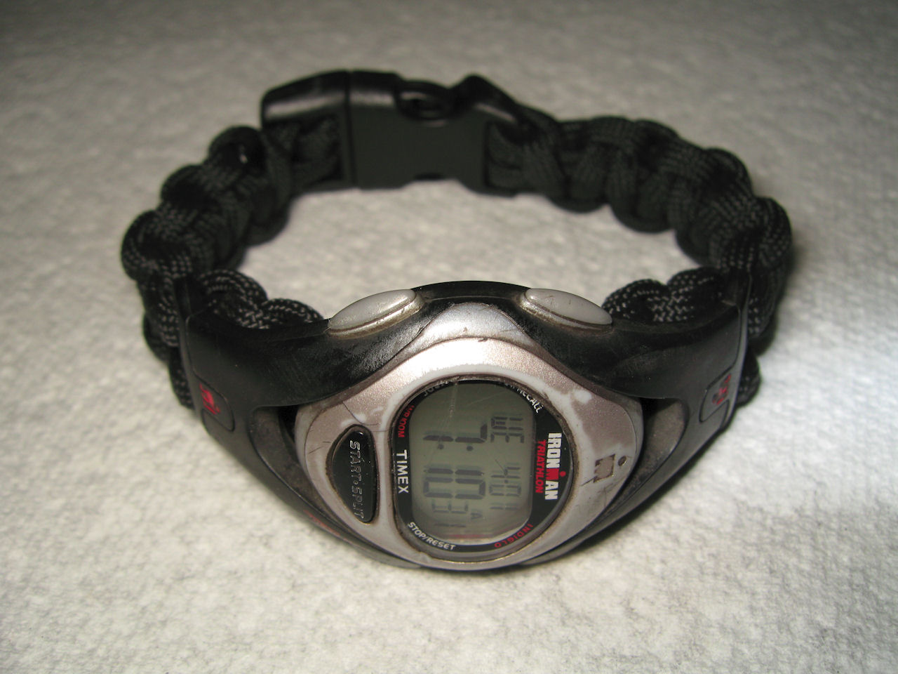
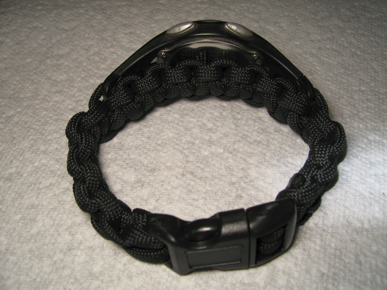
4-11-09
Dave's Paracord Watch Band
It only took me 3 tries to get this thing right.
I had to redo it to get the right size and look.
![]()
3-9-09
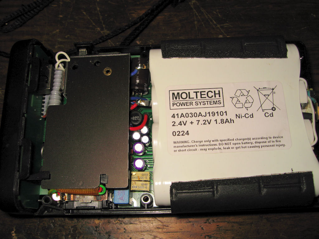
Metz P50 Battery Repair
I got a P50 battery for doing my brother's wedding
and use it about once a year and now my battery is
just flat out dead. I went to a local hobby shop to get
a custom battery made for it. It takes 8 Sub C cells.
In the middle of the pack is a thermal fuse and on either
side of the pack it has diodes in series which would be
used in reverse for temperature sensing. I'll post pics
later as I took some before and will take some after it
is working again with the new 3000mAh batteries which
I hope wont mess with the charging or metering. The
original battery pack is 1800mAh.
update:
3-10-09
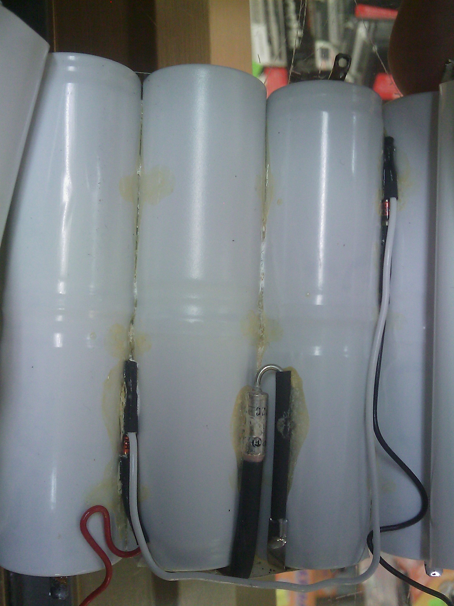
I got the new pack, what a disappointment. It had to be redone
the first time I seen it. After I picked it up the second time the
diode in it was broke. I tore it apart and marked down all the
parts that it needs. 8) Sub C batteries, 2) 1N4148 diodes, and
a 72 deg. C thermal fuse. I got the batteries in the pack for
now to see if I can get the metering set right. I'm discharging
the pack and then will recharge it again in hopes that the
bigger cells will work out for me. Pictures and info will
be uploaded as time goes on.
update:
3-11-09
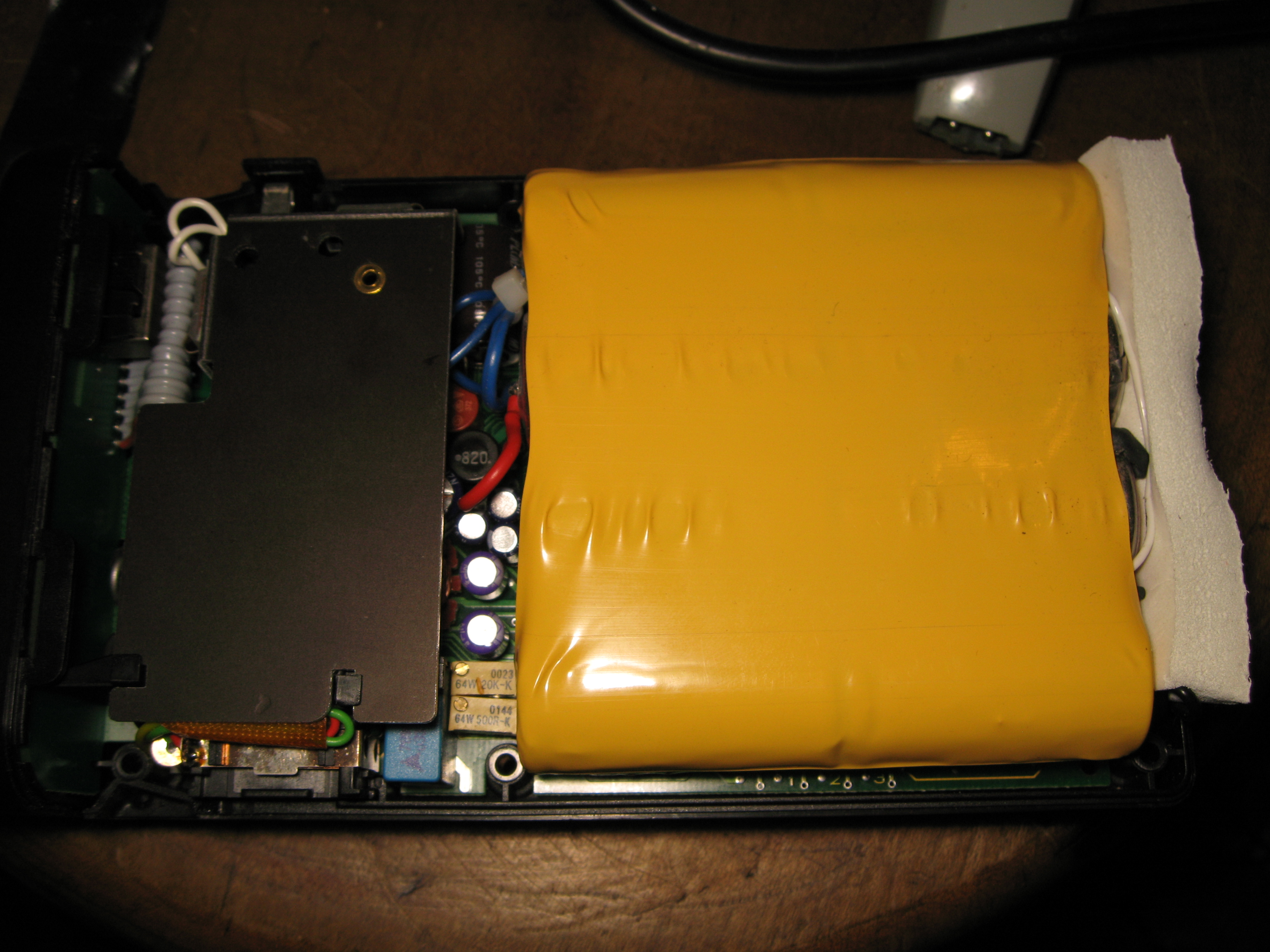
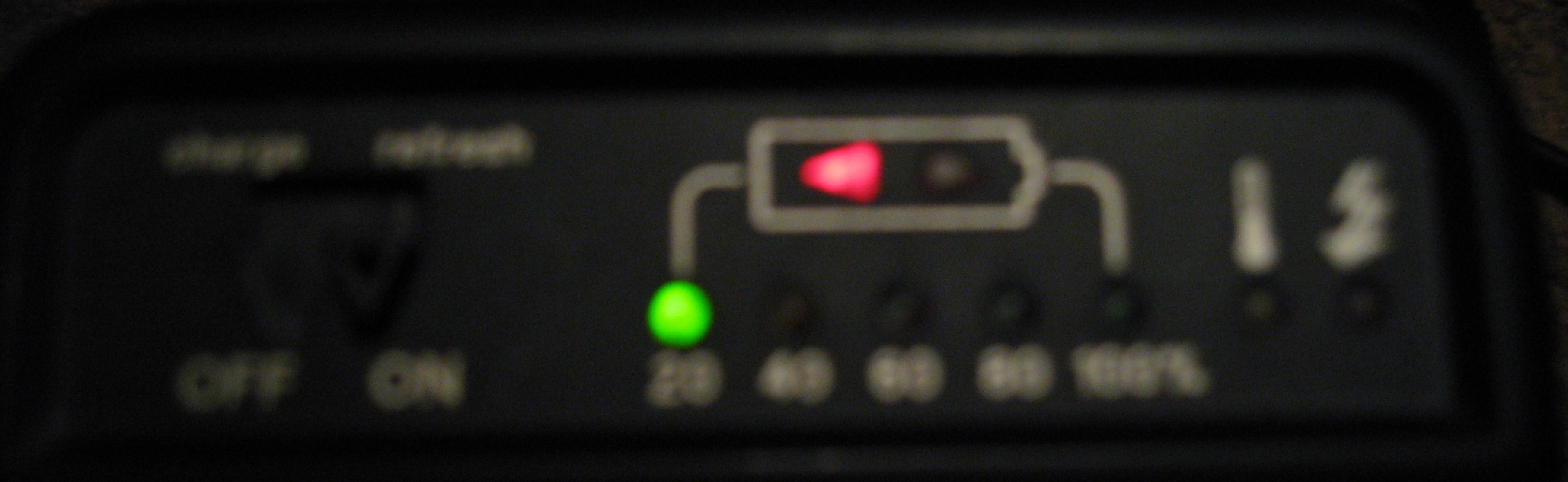
Well the overnight recharge test went well. I discharged the
battery and recharged it with the onboard uP and I had a full
bar on the meter. I then proceeded to finalize the battery repair
and put it back together to find it thinks my battery is dead
again. I guess when you disconnect the battery it defaults
to a dead battery. So a recharge is back in progress and
the final test will be later this week when I shoot a few
basketball games and see how the battery does.
Ok, last pic was kind of blurry
Update:
3-15-09
Wow, I took pictures for 5 1/2 hours with the new
batteries and still had 20%+ life. I took 909
pictures using 800 ISO and f5.6 in a well lit
gymnasium. I'm pretty happy with my new found
pack. Last year I took 670 pictures at the same
place and the last 70 pictures I had to use AA
batteries as the pack went dead. So the 3Ah
batteries made a good replacement for the P50.
Update:
7-26-09
If you get a dead battery pack after installing new
batteries ( which you probably will ), you need to
put the battery pack into an overnight discharge
recharge cycle. Turn the pack on and then plug
in the power cord which should give you the
discharge light. My pack took 12 hours to go
through the cycle until I got a fully charged
battery where the indicator shows full charge.
If you have a new or old pack that seems to
have a problem with "overheating" where all
the lights flash all the time and then it wont let
you take anymore pictures you need to check or
change the internal diodes on the pack as that is
what I had a problem with. I changed the bottom
left diode and the problem went away.
![]()
3-1-09
Aaron's Xbox 360 Repair
I got another xbox to rip apart and see if I can
repair. I'll keep the progress posted here.
updated:
3-3-09
I installed the newer fix for this xbox and still got
the RROD so I still had to do the overheat to get
it to work. On for 6 hours so far and all is well.
![]()
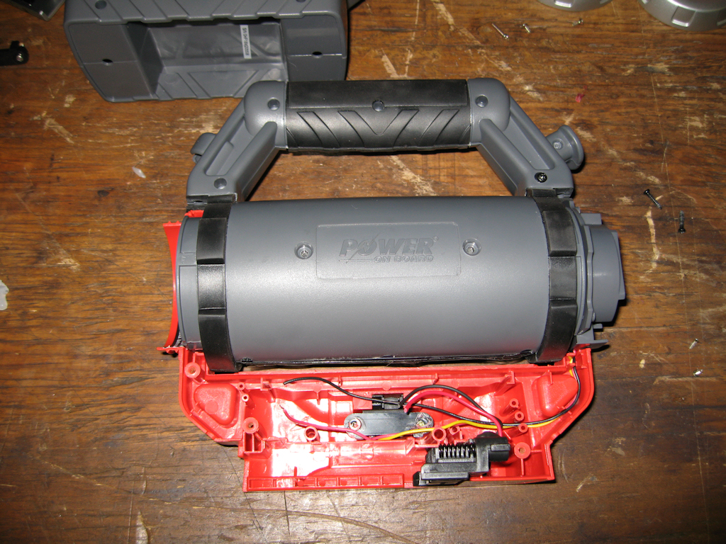
1-28-09
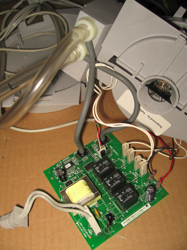
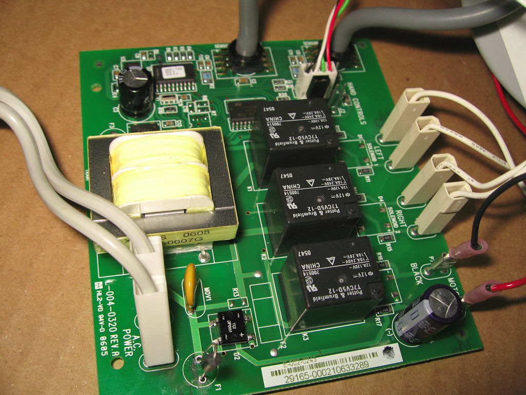
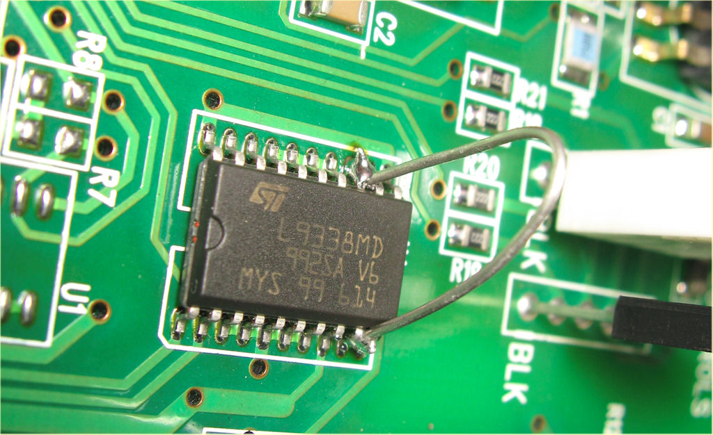
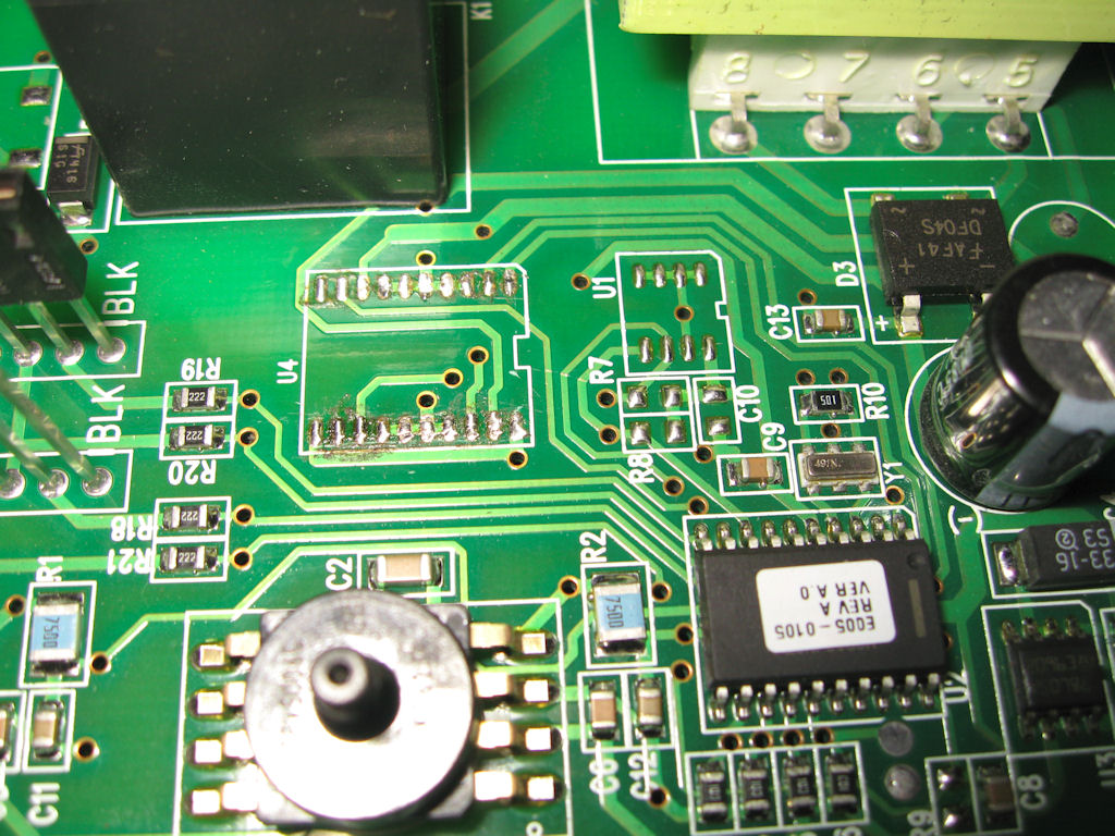
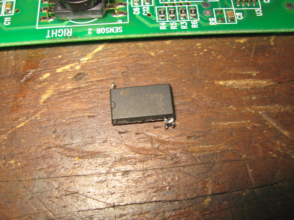
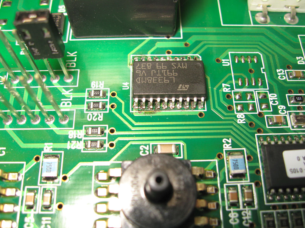
Dave's Sleep Number Bed Pump repair
Here is some pics of a sleep number bed pump
that wasn't working. I replaced the diode bridge
and am waiting on parts for the quad buffer chip
to get it fully functional as the pump wont come
on without the chip.
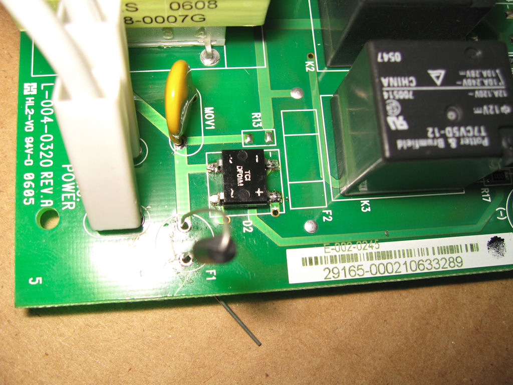
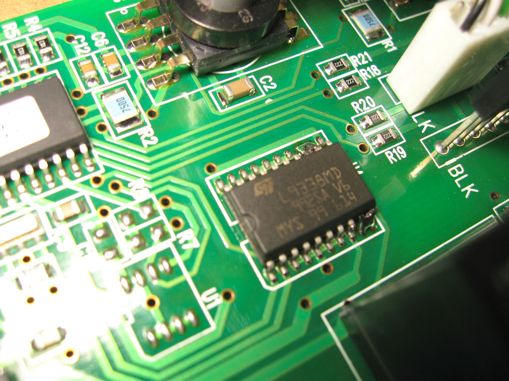
update:
2-12-09
I installed the new chip and presto it is as
good as new, or at least functional anyway.
I cut the old smt chip out with my knife
then desoldered the legs so I could solder
on the new chip. I should have installed
diodes across the coils to reduce the chance
of destroying the chip again.
![]()
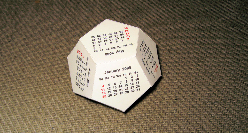
1-5-09
Paper Models
Here are a couple of pics from my paper
models I've made. I started out slow and
plan on making the shuttle and airwolf models.
![]()
10-25-08
Xpadder Files
Here are my files I used for some of my games.
Too bad xpadder has been discontinued.
![]()
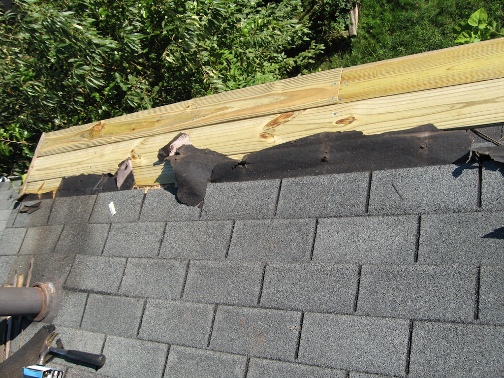
10-18-08
Roof Repair
Windy weather tends to destroy stuff so
here is the before and after pics
![]()
10-18-08
LED light mod
What do I do when I have an 18v flourescent
light and wish it was an LED one? Modify
the one I have so it is LED version. I took 2
units combined to make my Black & Decker
18v slide battery work with my new LED light.
![]()
8-03-08
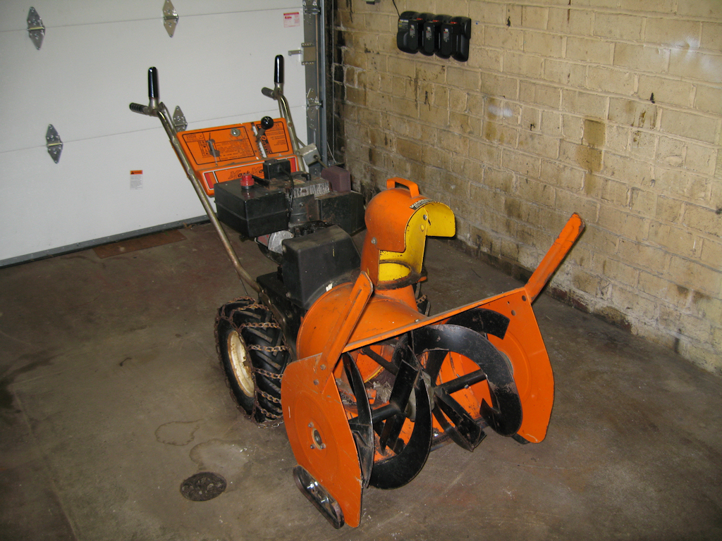
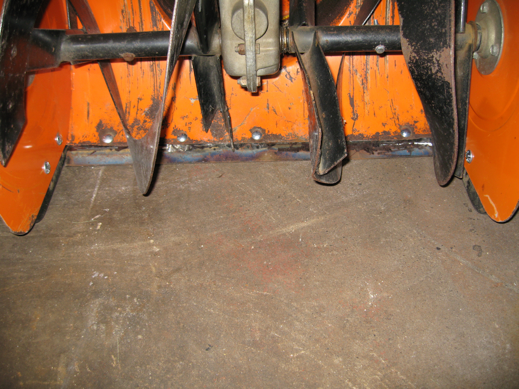
Snow Blower Repair
I sucked up a few bricks into my chute on the
old snowblower and also had the blade wear
out on one site so I had to fix it. I can't drill
square holes so cutting off the bad and then
welding on a new piece of flatstock sounded
like a better idea and here are the pics of the
repair.
![]()
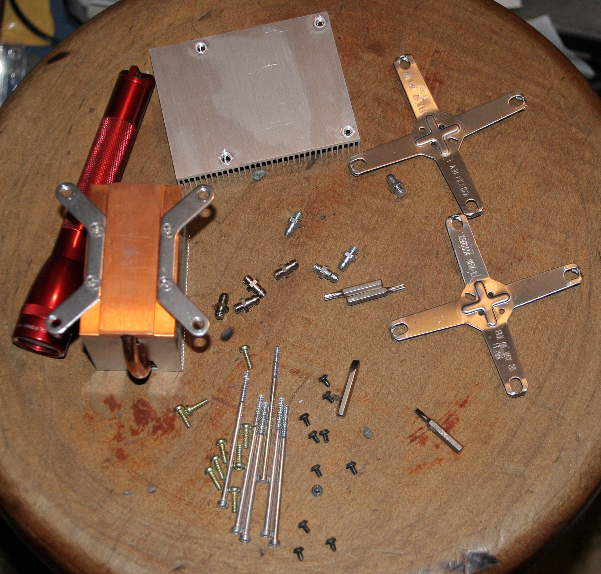
7-27-08
Larry's XBox 360 Fix
ok, I usually post fix titles after I actually fix them
but this time I'm going to post as I go and just
hope I can fix it. So far I got it ripped apart and
now need to clean up the cpu's before going any
farther.
Update:
7-30-08
IT WORKS!!! I added washers to the bottom of the
motherboard before the Xclamp, overheated the
processors and let them cool and presto! functioning
again. I played it for over an hour with no trouble at
all. Here are some pics after it was working
![]()
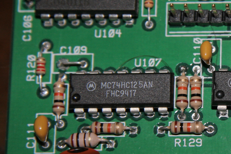
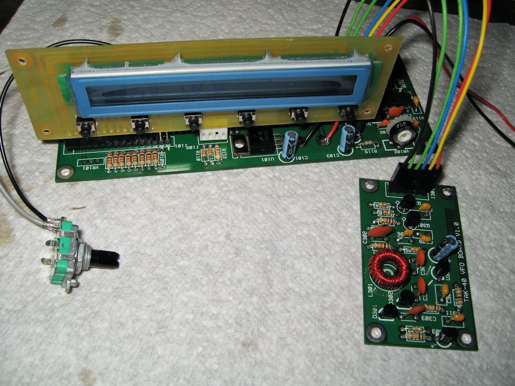
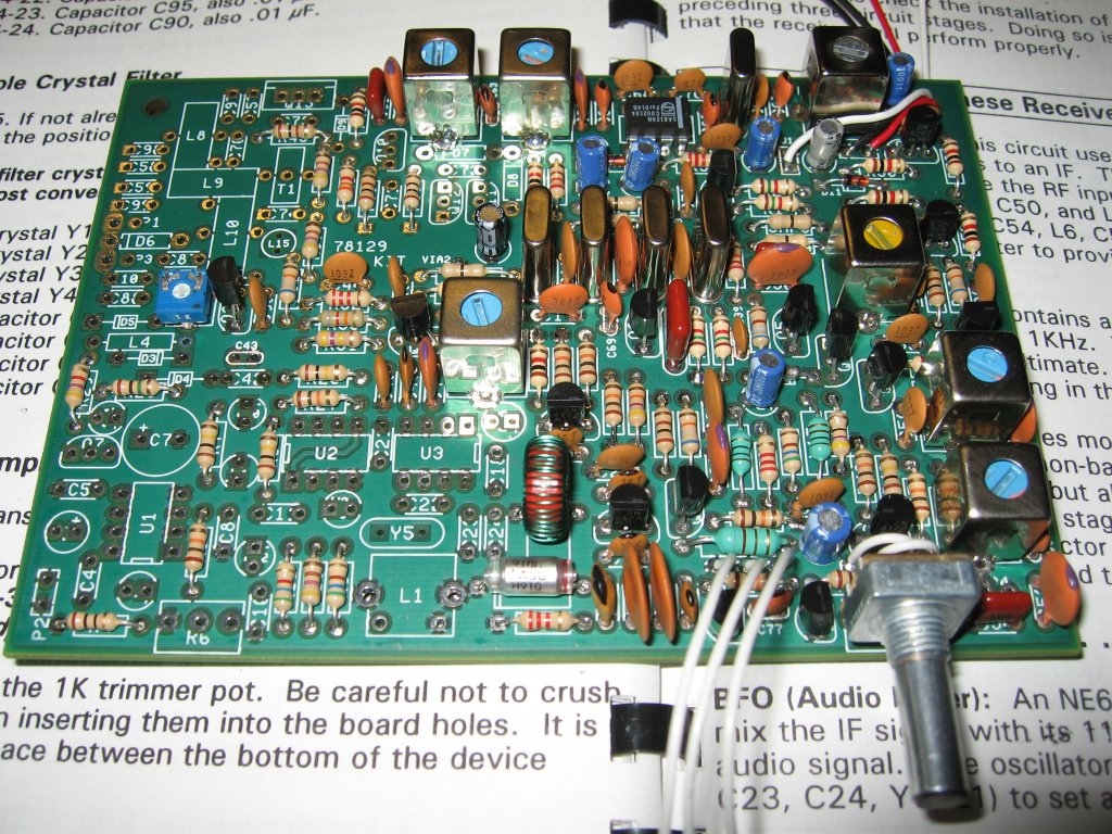
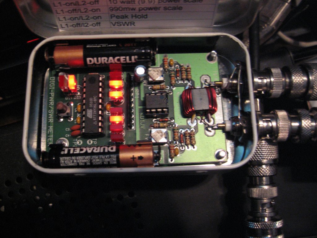
7-22-08
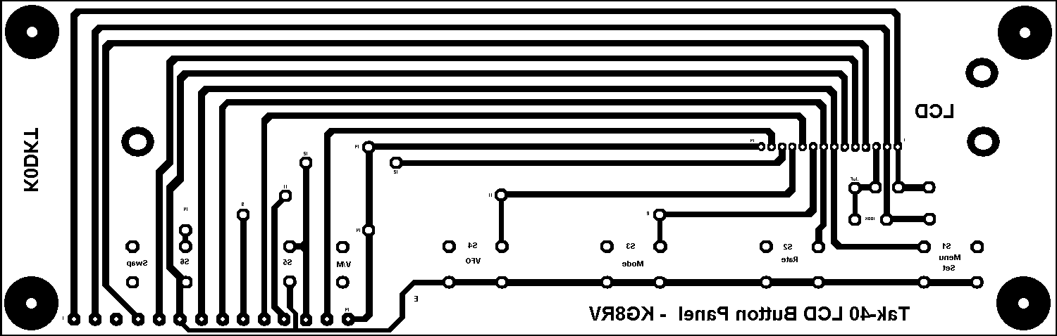
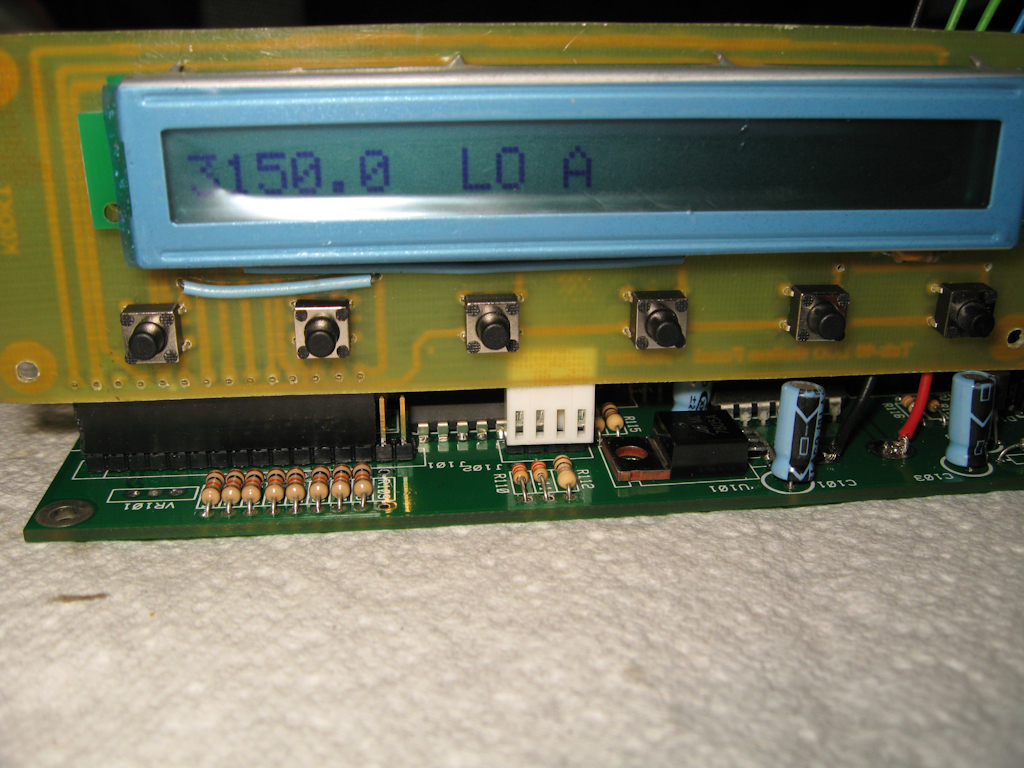
Tak-40 Kit (KD8DFL version)
I'll be starting the construction of my Tak-40 radio
kit soon and will post info here as I go.
update:
7-23-08
I got my kit today and started looking over
the parts. Looks pretty cool so far.
update:
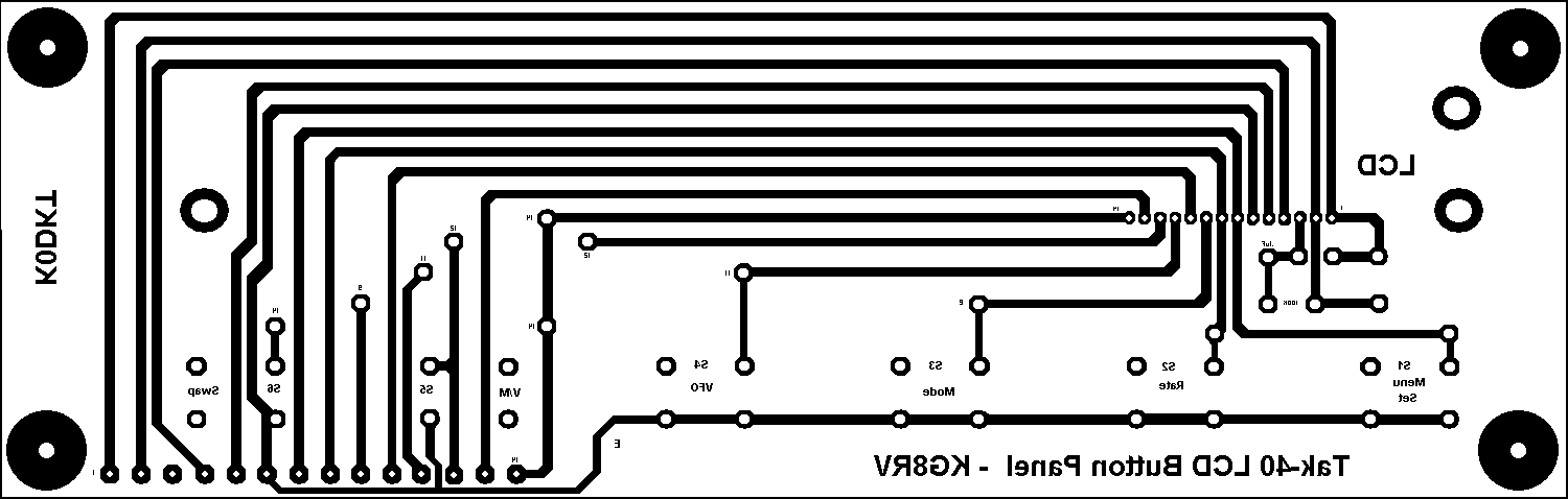
7-27-08
I found a couple of errors in labeling that
wasn't documented so I fixed those and
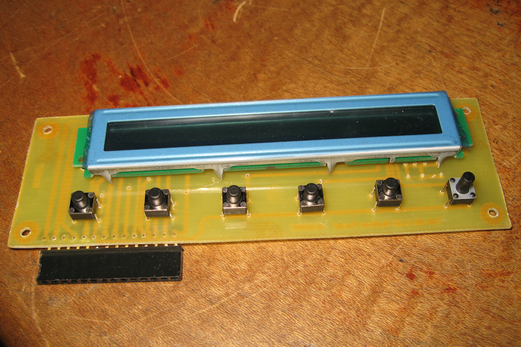
now I'm going to make an lcd/button panel
which I got the original design from K0DKT
Here are his origninal pdf files that I got
his permission to make available. I'm
also making available the bmp file I used
to make mine which is only single sided.
Version 2:
this bmp file removes 2 unused solder pads
and lowers the resistor & cap to better fit
by the lcd.
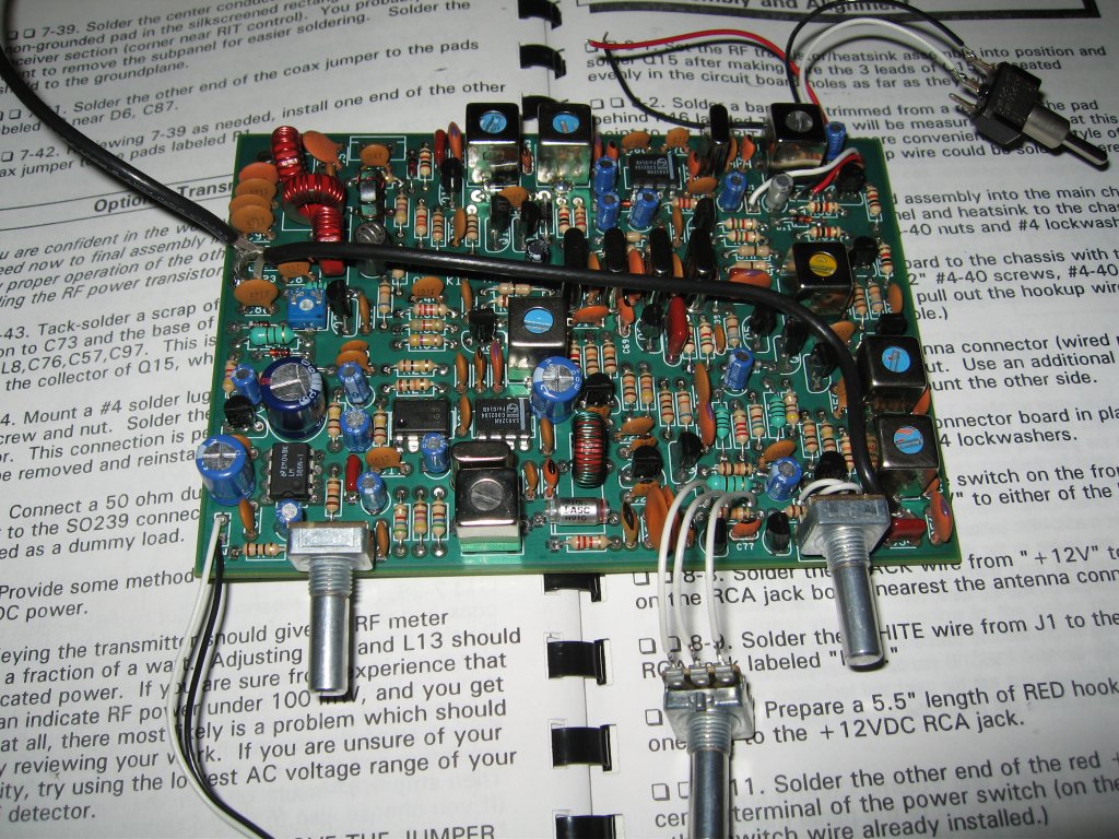
update:
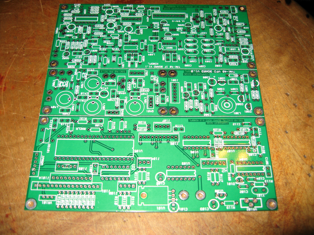
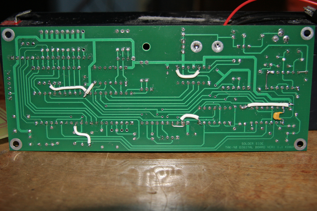
7-30-08
I got the display board etched and drilled
and now I need to get the parts installed.
update:
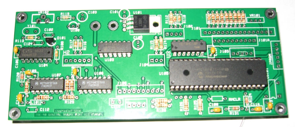
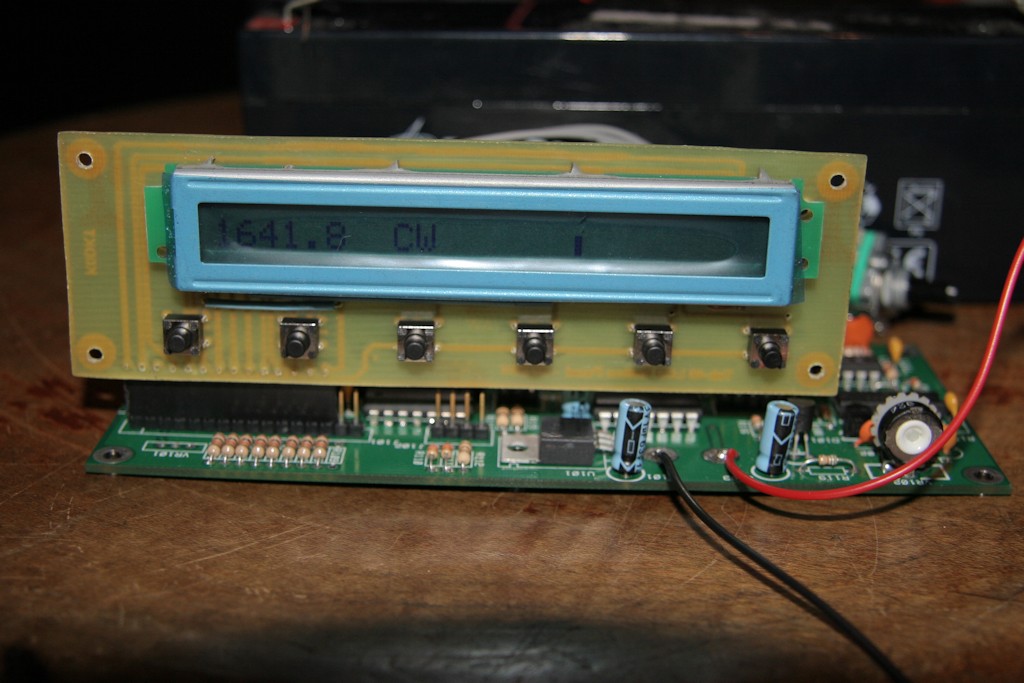
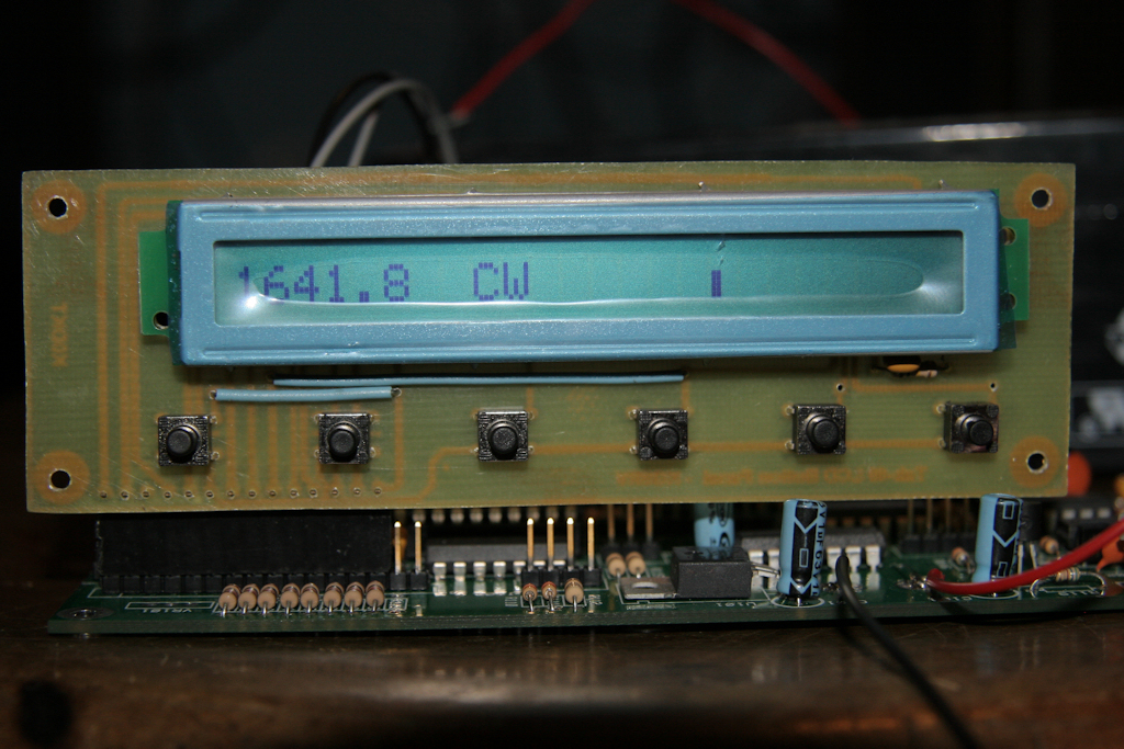
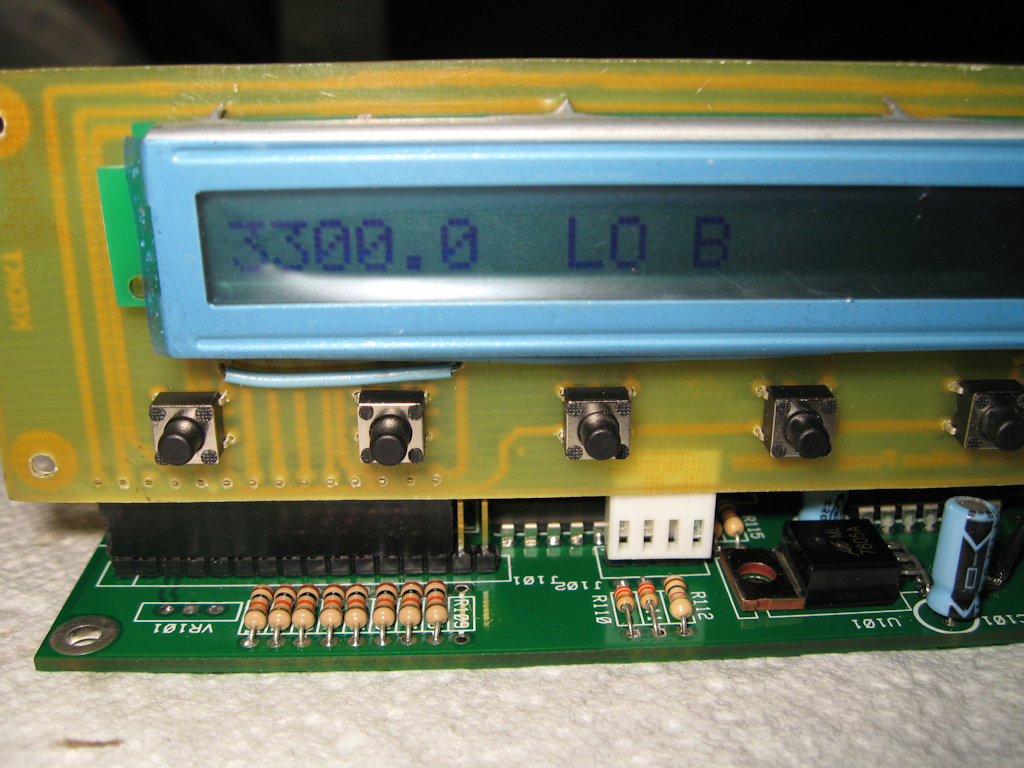
8-6-08
It's working!! Somewhat, I only have the digital
board and the display board done and powered.
So now I can verify that my single sided bitmap
version of Wayne's display board is working.
Here are some more pics of what I have.
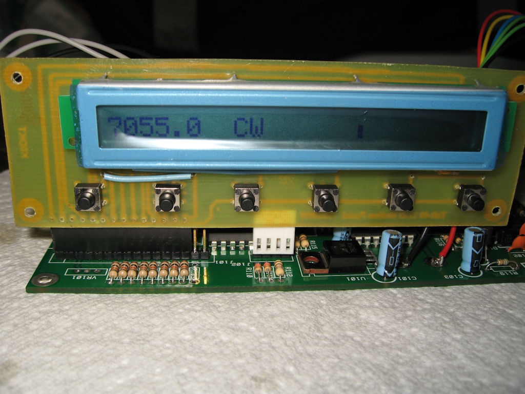
update:
8-8-08
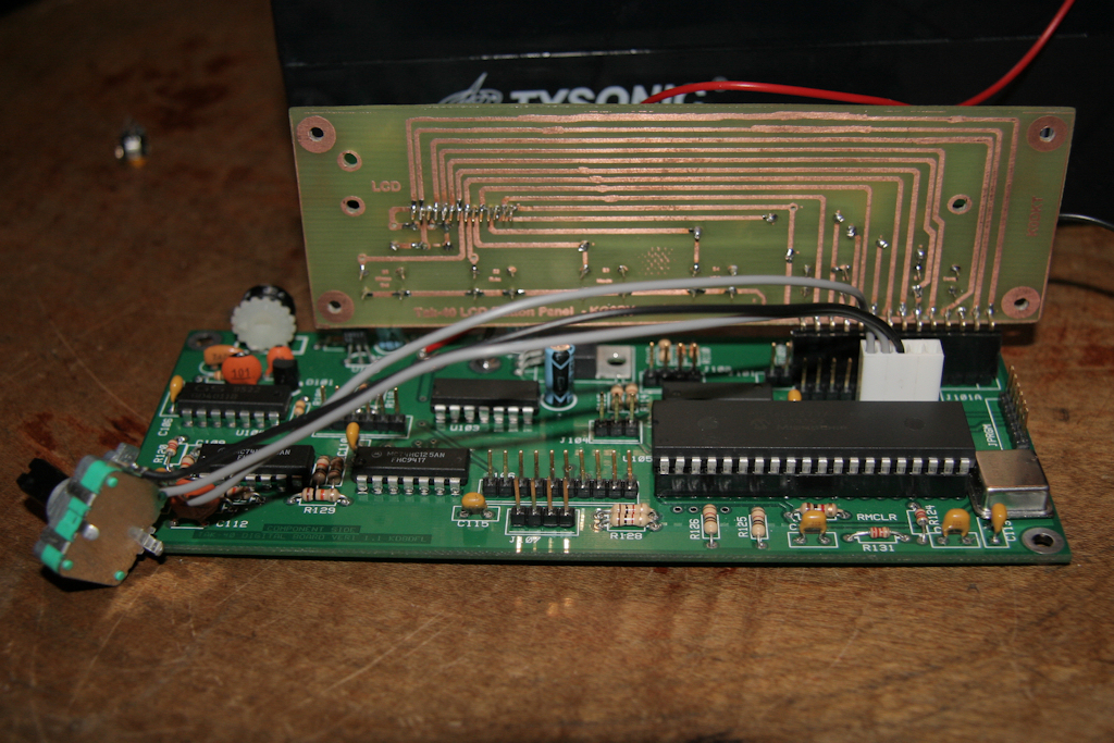
Caution! I hooked the up encoder to the wrong
plug so don't go off of my pictures for encoder.
Encoder should be under display board which
it is now so all future pictures after (8-8-08)
will be correct! I had hooked it up but never
tested to see if it works and of course it didn't in
its current location but I have it working now.
It is getting more exciting now the closer I get!
Encoder is wired in wrong spot!
Black wire should be red!
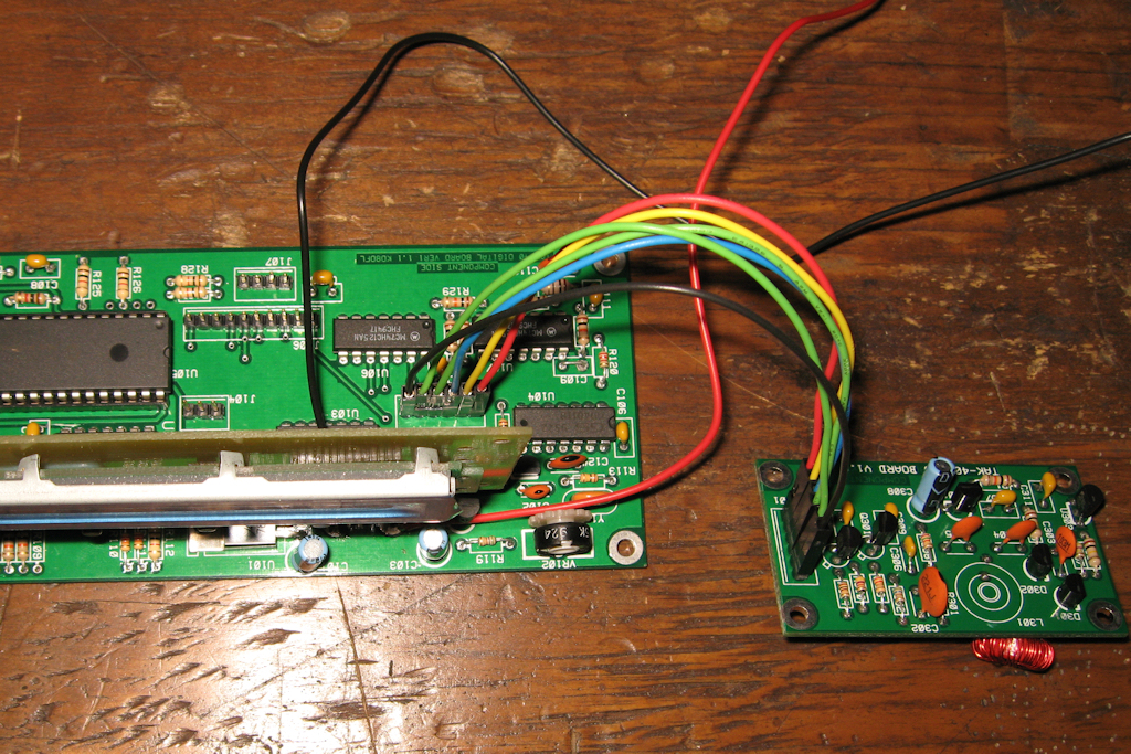
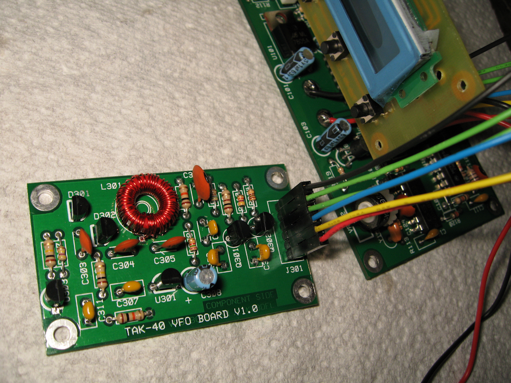
update:
8-8-08
I now have the VFO board done and the coil
wired up temporarily. I used jumpers to wire
it as I don't want any permanent connections
until I know what box it is going in. The ones
I find that I like are $26 and I'm hoping to get
a cheaper one.
update:
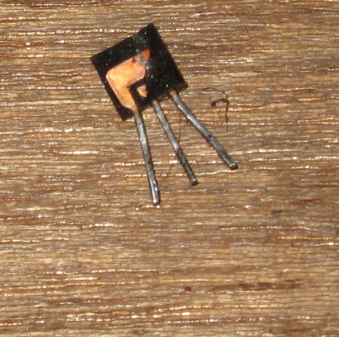
8-9-08
I now have a functioning VFO. I had the
transistor in backwards as the silkscreen
was for a different part # and my guess
was wrong(see above). I looked them up and had to
turn them around. I also missed the + jumper
for the transistor. I got it all setup, wound
for the correct range and need to move on
to the next step. Here are some pics of
my progress so far.
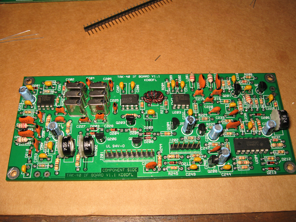
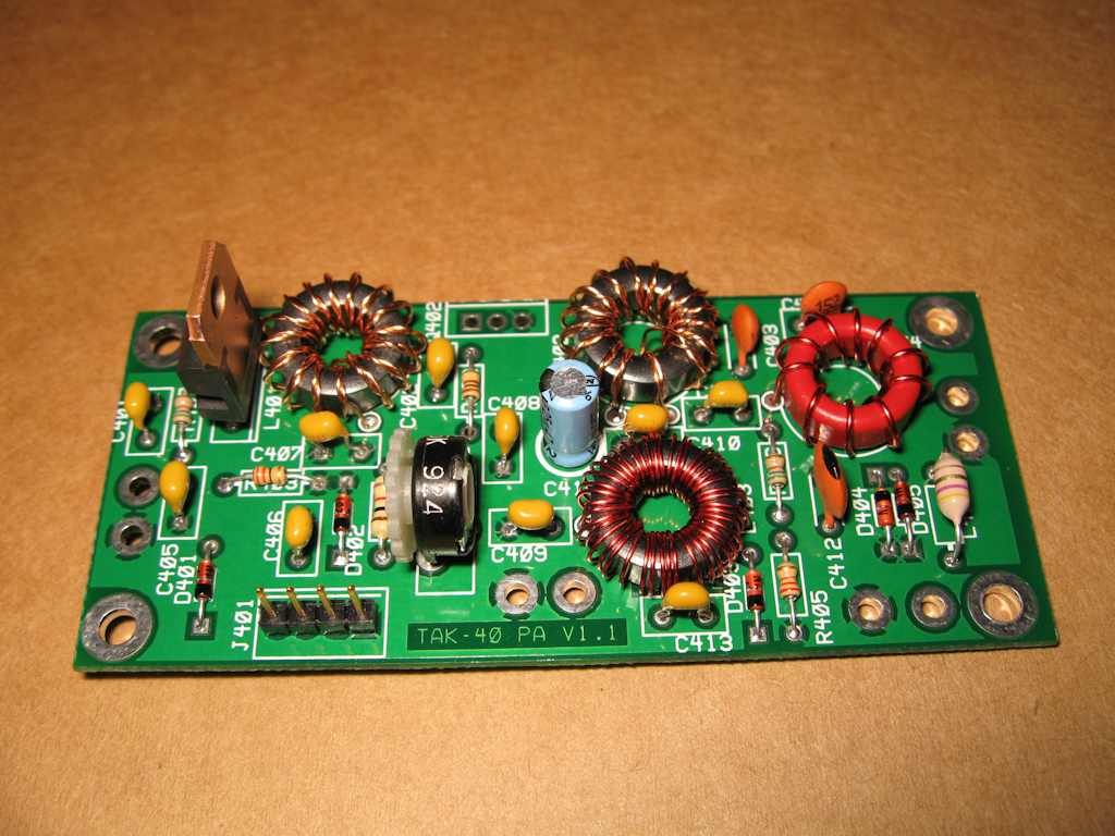
update:
8-12-08
I got my last 2 boards finished and a
cable wired. Now all I need to do is
get it working and on the air.
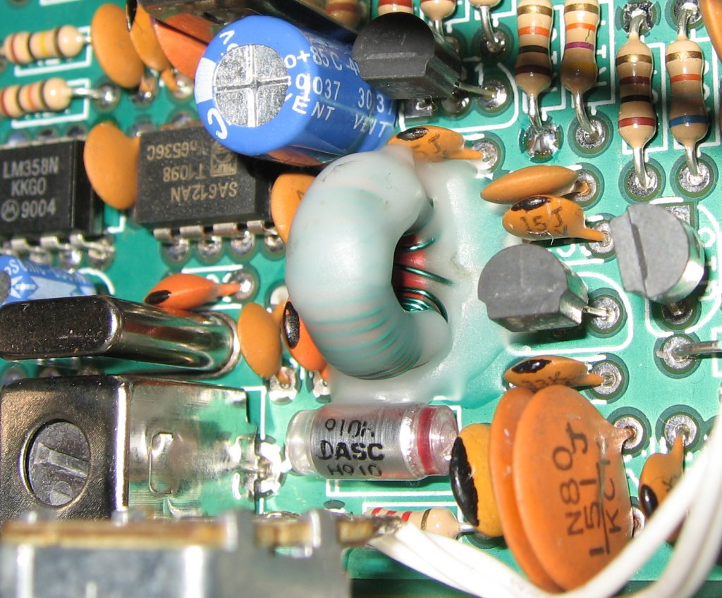
bifiler winding check (9 turns)
update:
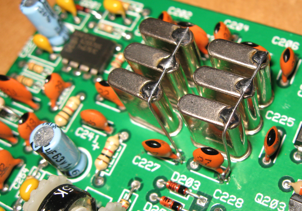
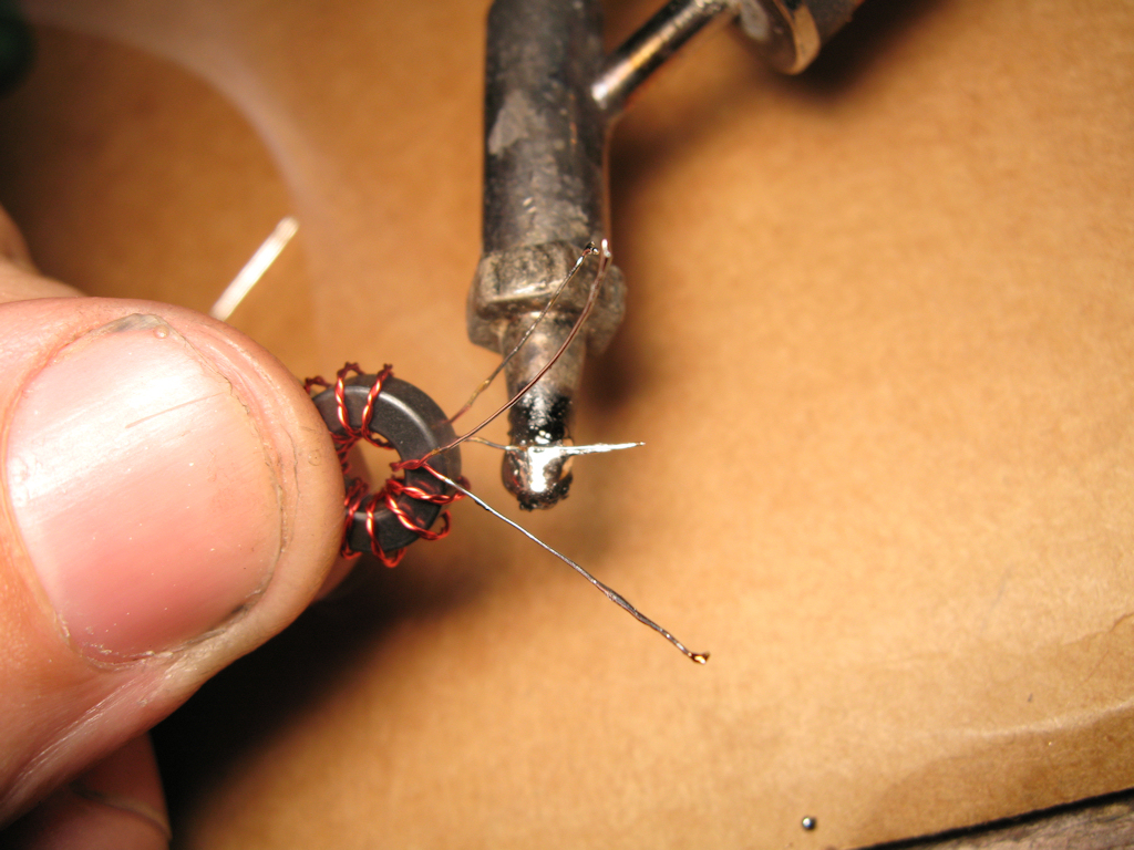
8-14-08
How to clean toroids of varnish with a big
soldering iron and some solder. No sand
paper required. This makes it really easy
to clean varnished wires and also tins them.
update:
8-18-08
Bummer!
Ok, now I have all the boards done and
no audio output. So I guess I got a bit
of troubleshooting to do. I got a bit of
a signal on my O-scope but I will need
more work to find the problem.
update:
8-24-08
Got some help on voltages for different
pins and found a wrong size component
and replaced it and also calibrated the AGC
but now I'm hearing an oscillation in the speaker
so I may just have to add my shielded wires I was
avoiding until I got a box for the rig.
update:
8-28-08
Well, I hooked up my rf gain again and my pulses
went away. If I turn it down to open it the gain up
I can still hear it but will work on that later. I hooked
up a 2 meter antenna just to give it an antenna and
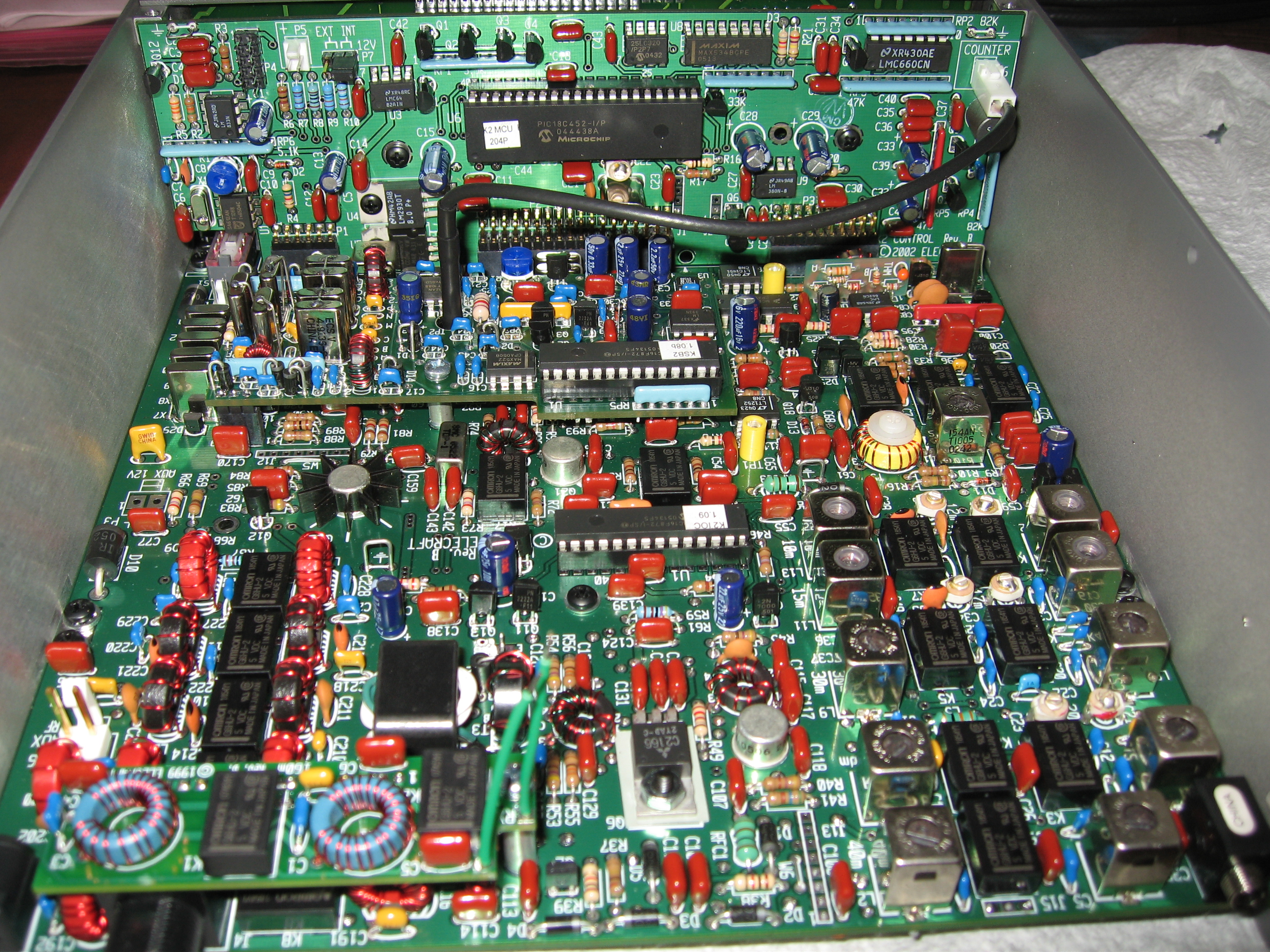
keyed up my Elecraft K2 radio and low and behold
I can hear CW!!! I still want to get the pulsating out
before going much farther but it does seem to work.
So maybe I'll hook up the amp and see if it'll tx to
my other radio. Then it will be time for a box? Not
sure where that will come from or if I build one from
scratch.
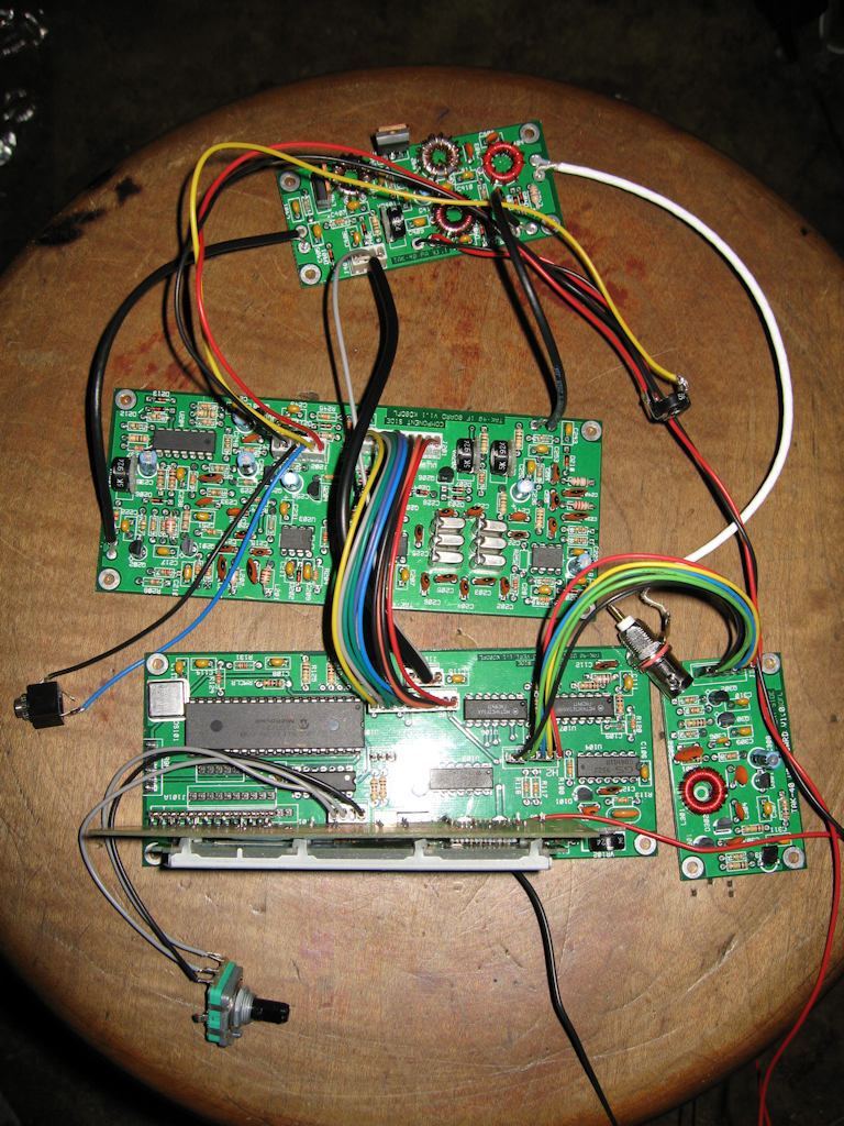
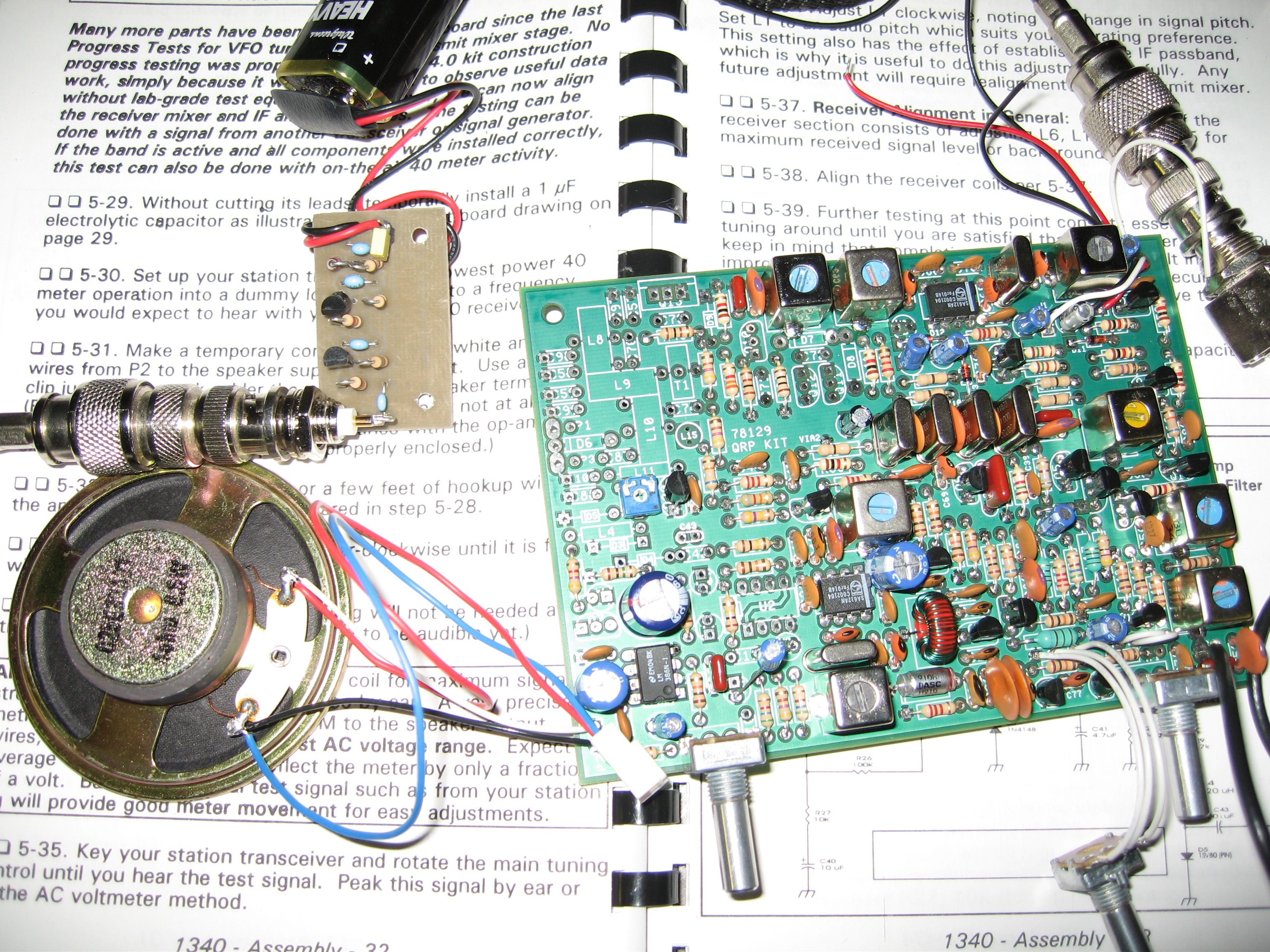
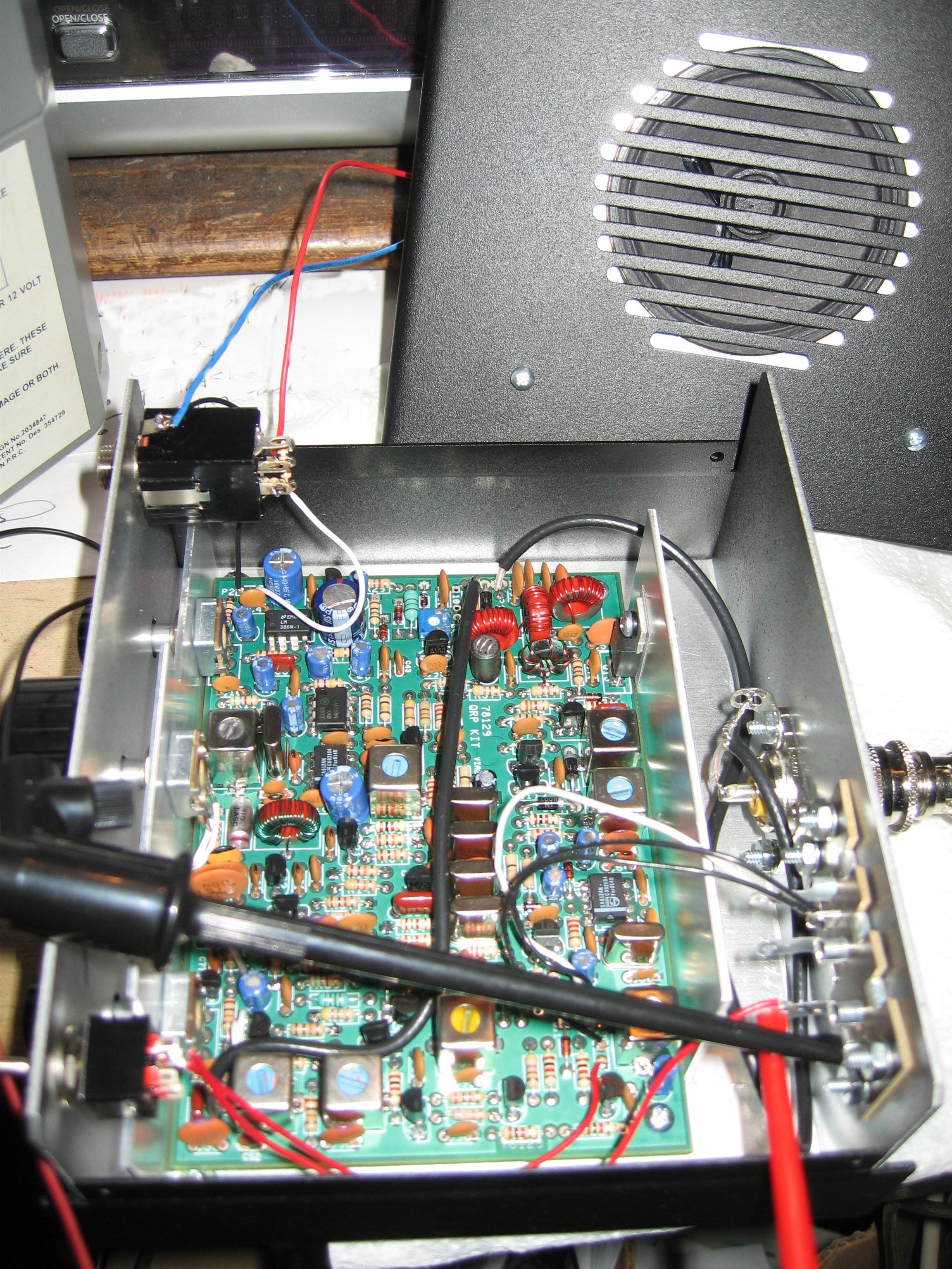
update:
9-4-08
IT WORKS!!!
Ok, I still got work to do on it but it does rx and now
even tx. I used my fingers as a heat sink and shorted
the PTT and tuned in my other rig until my fingers got
warm and unkeyed. I did this until I was able to tune
into the cw. I still have the pulsations when I turn up
the RF gain pot or down? however you want to look
at it. Here are some pics or pic of my temporary hookups.
I still need to shield some of my wires and VFO which
will probably end my osc. problem but no smoke test
has been finished. Once I get working on it again
and change my wires and add a heatsink I need to
align it.
update:
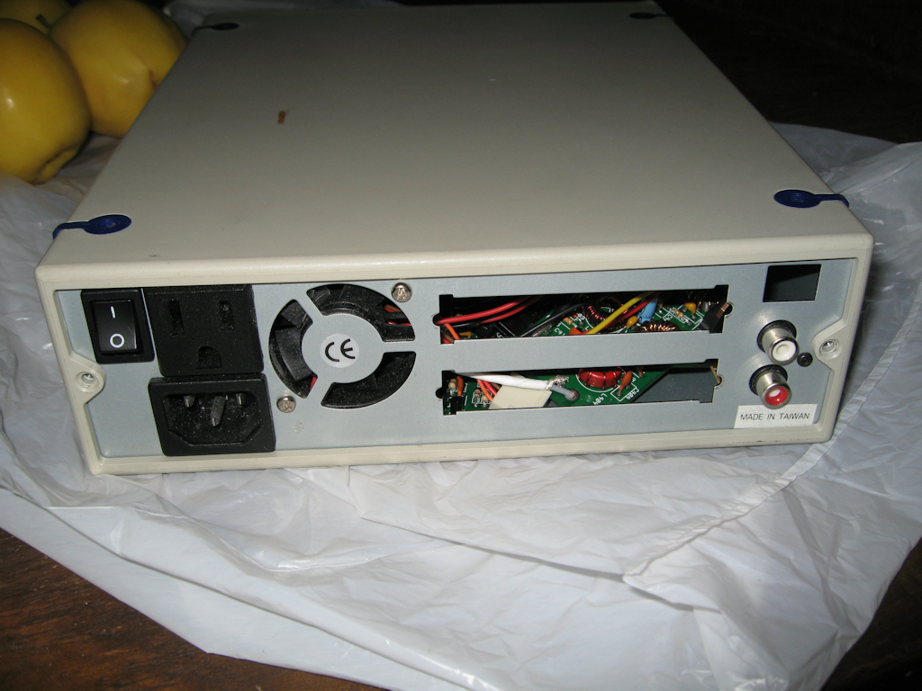
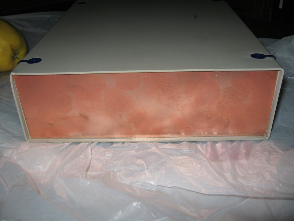
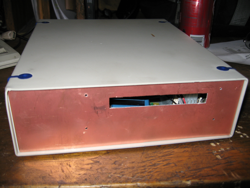
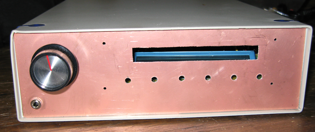
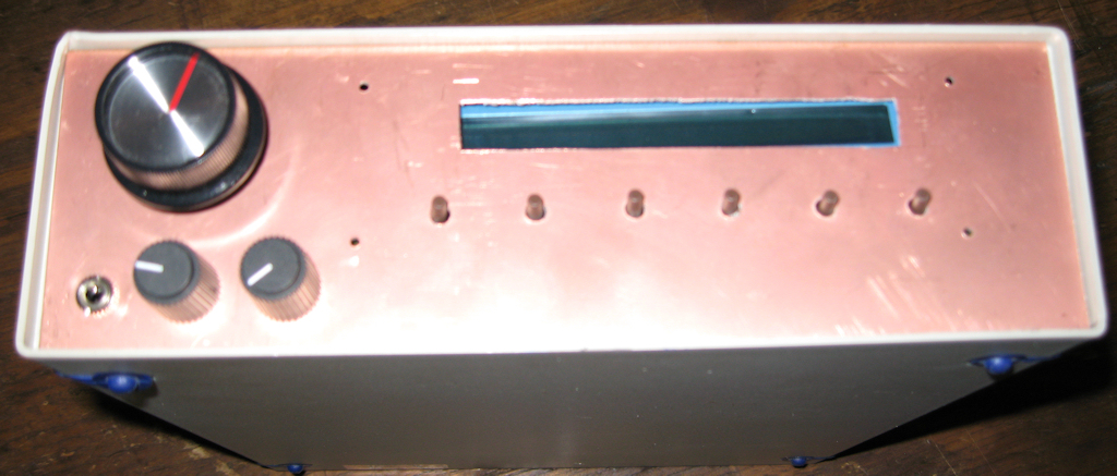
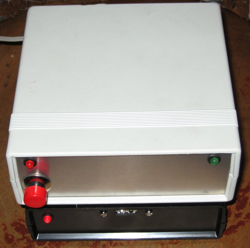
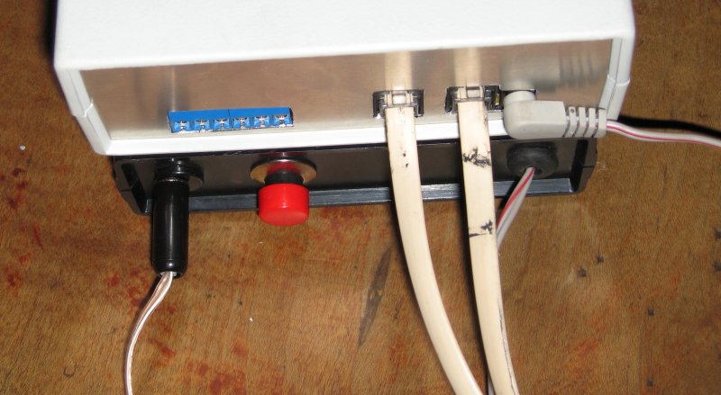
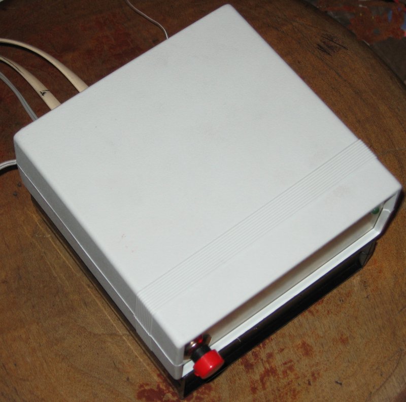
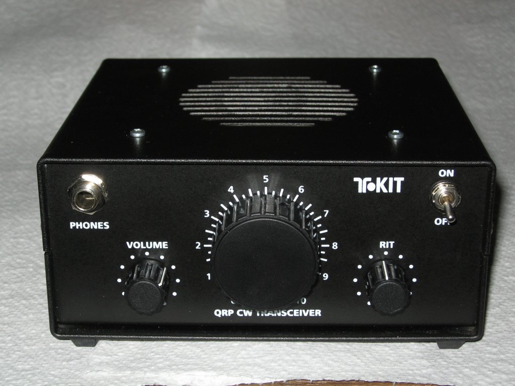
9-12-08
I think I found a case. I'm using an old scsi case which
has a power supply built in so I cut copper clad board
to use as a face and will do the same for the top and
back when needed. It might not be permanent but it
is a home either way. Here are some pics.
![]()
7-11-08
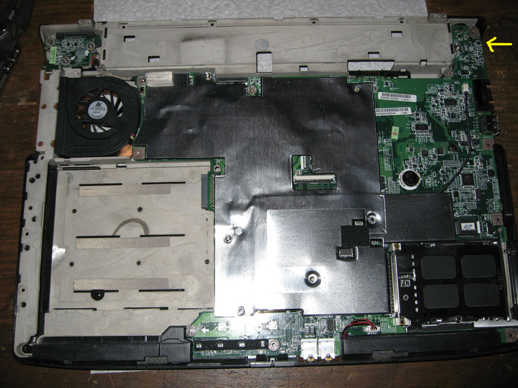
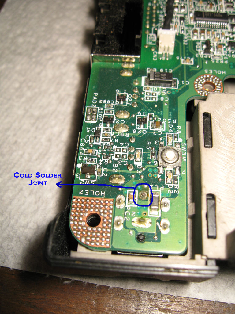
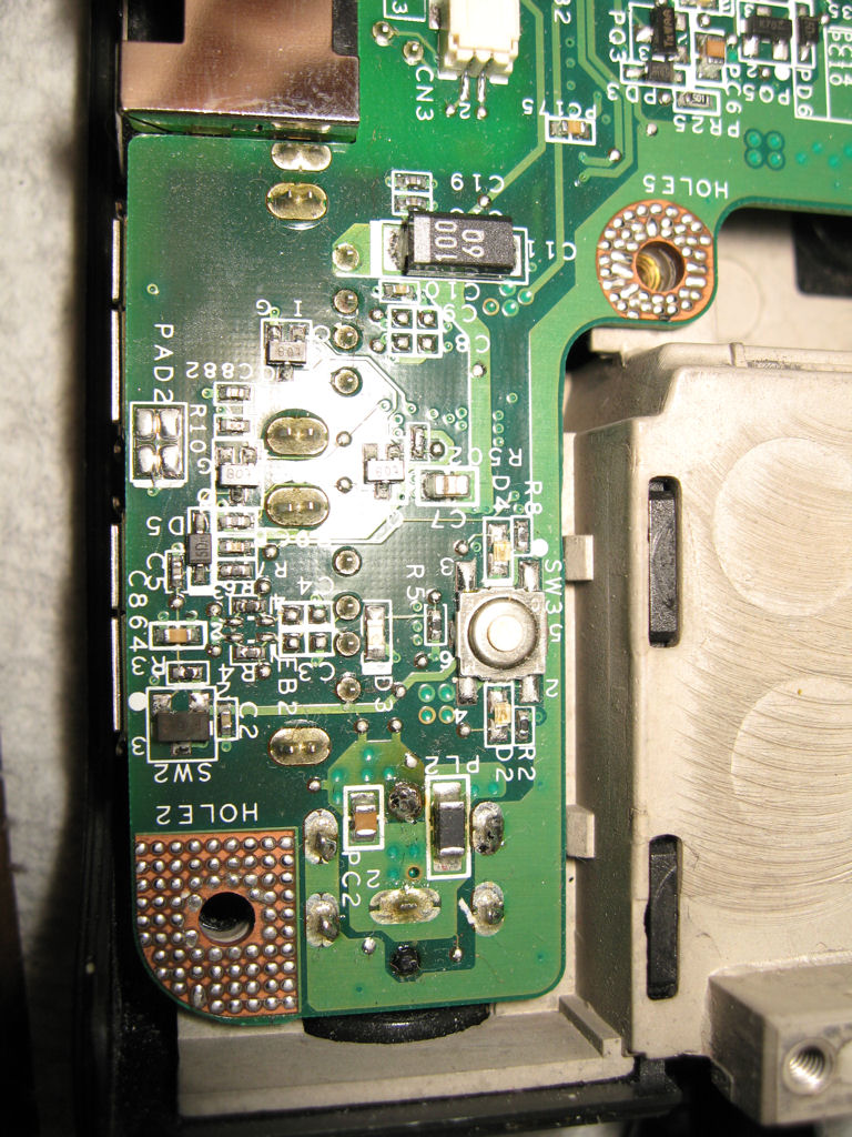
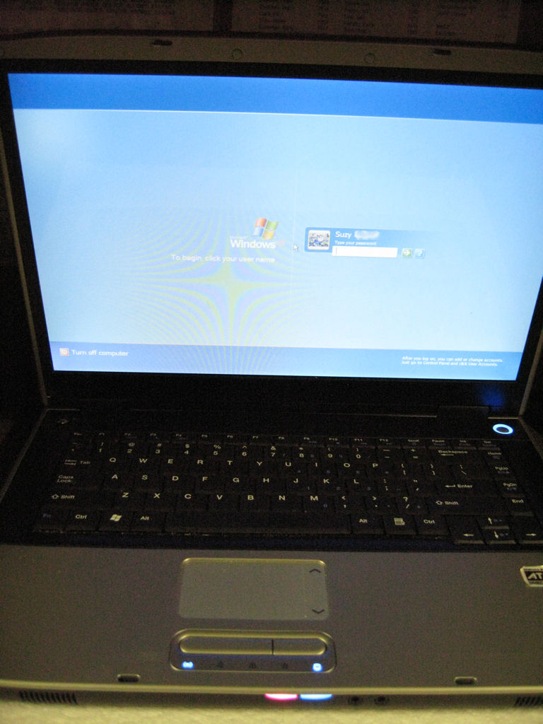
Suzy Laptop Repair
Yet another bad design for laptop power.
I fixed the power plug on the laptop on another
laptop. Here they are.
![]()
7-9-08
Halo 2 PC/Vista
I uploaded the 2 files I used for achievements
for h2vista which you load for the Halo 2 dedicated
server. Even a silver account can host the file. Just
start h2server load the custom playlists and wait for
2 other players to start the game. Get through all of them
and you have a new achievement. Then do the other one.
I couldn't fine one on the internet so I created it and I hope
someone gets some use out of it.
![]()
7-3-08
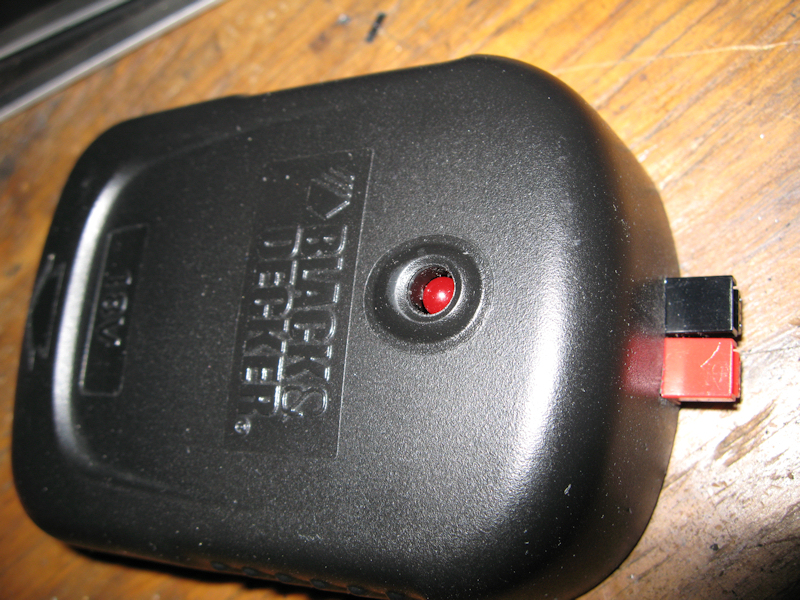
Battery Adapter
Here I used an old battery charger adapter
as the basis for an adapter so I can use my
18v battery with 12v equipment.
![]()
6-21-08
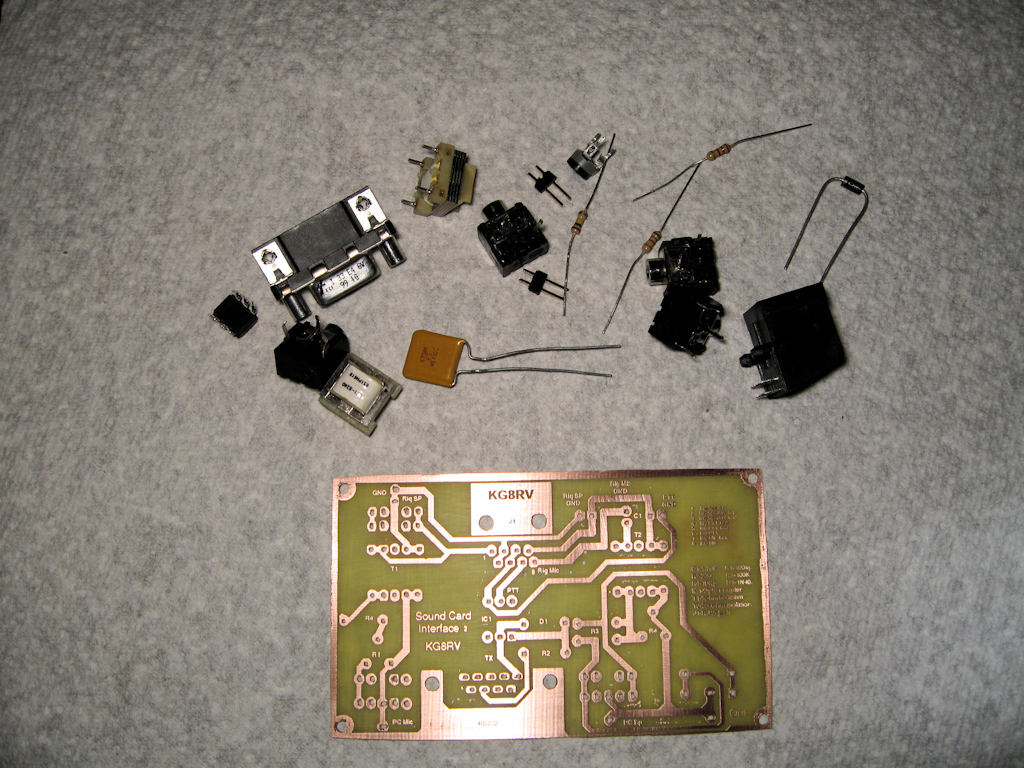
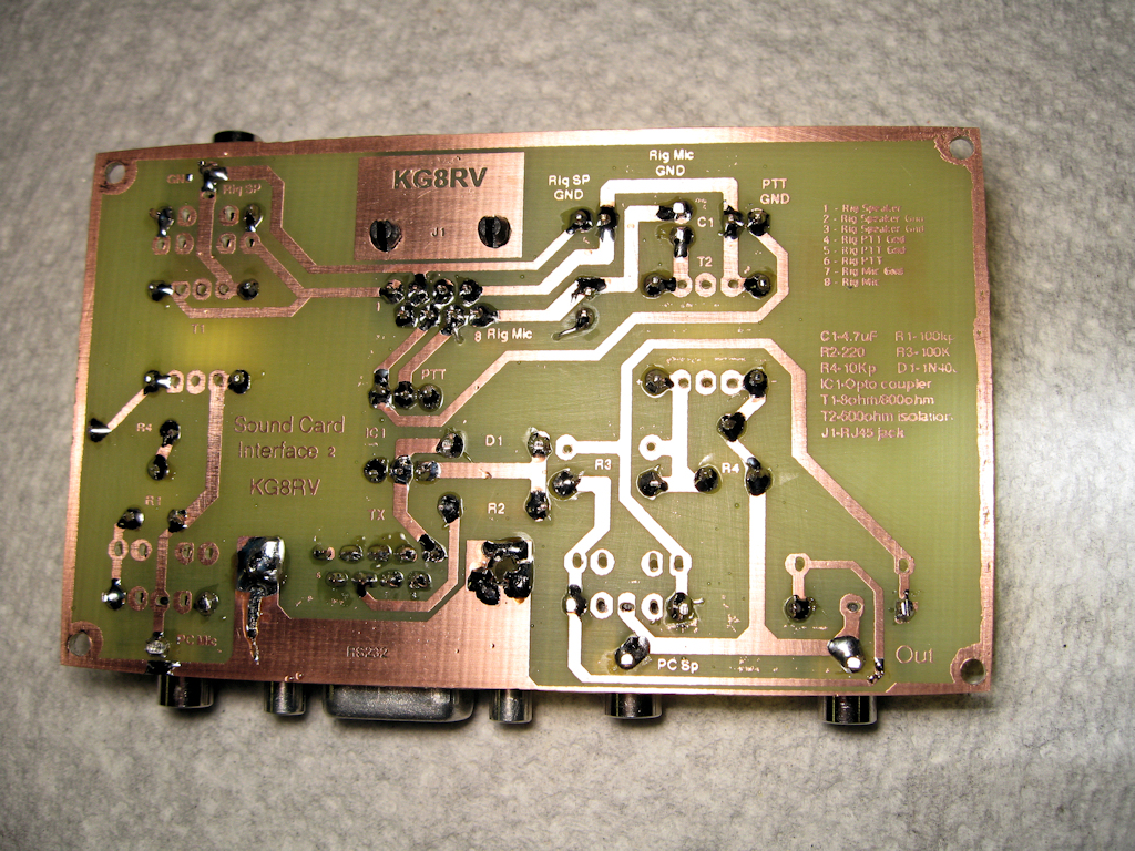
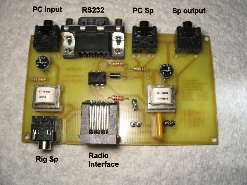
Sound Card Interface
I took a circuit board for the packet sound
card interface and made it so I don't have to
use wires tied to the board. I added jacks all
the way around it.
update:
7-9-08
I uploaded pics of finished project which should
work on echolink or packet as described in the
above link for the original board. I have tried this
board using simplex repeater software and
it worked very well. His main site is here.
drawing
![]()
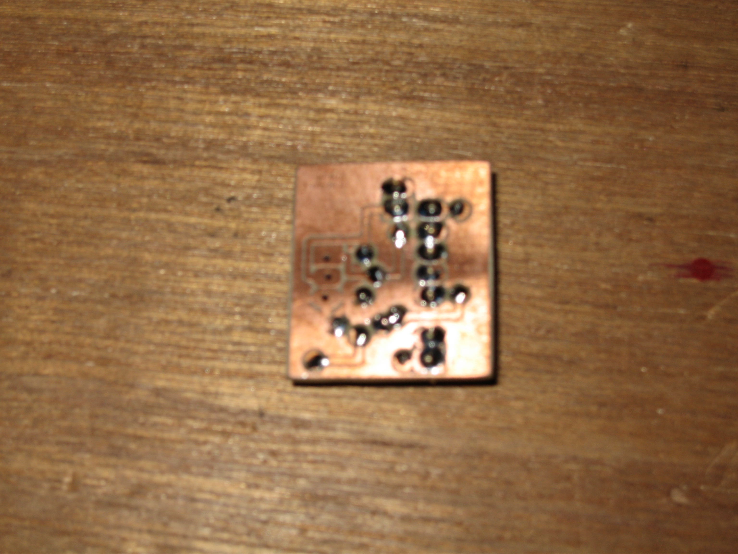
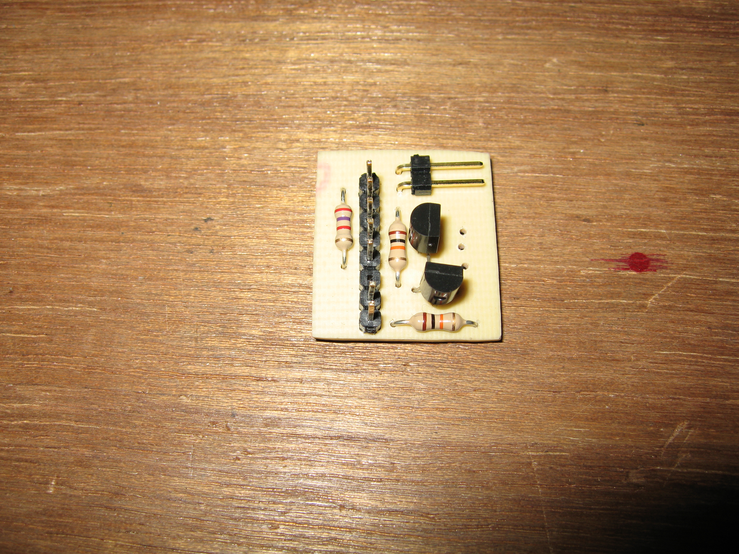
6-03-08
LC Meter with LCD Display
I etched some boards for construction of an
LCD type LC Meter. More info as time goes on.
![]()
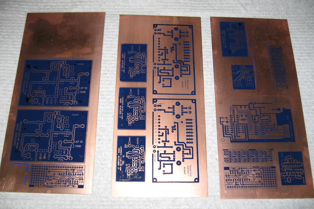
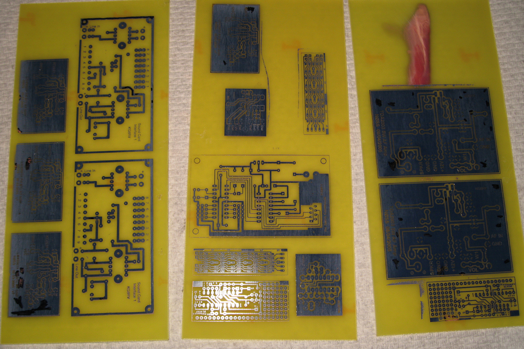
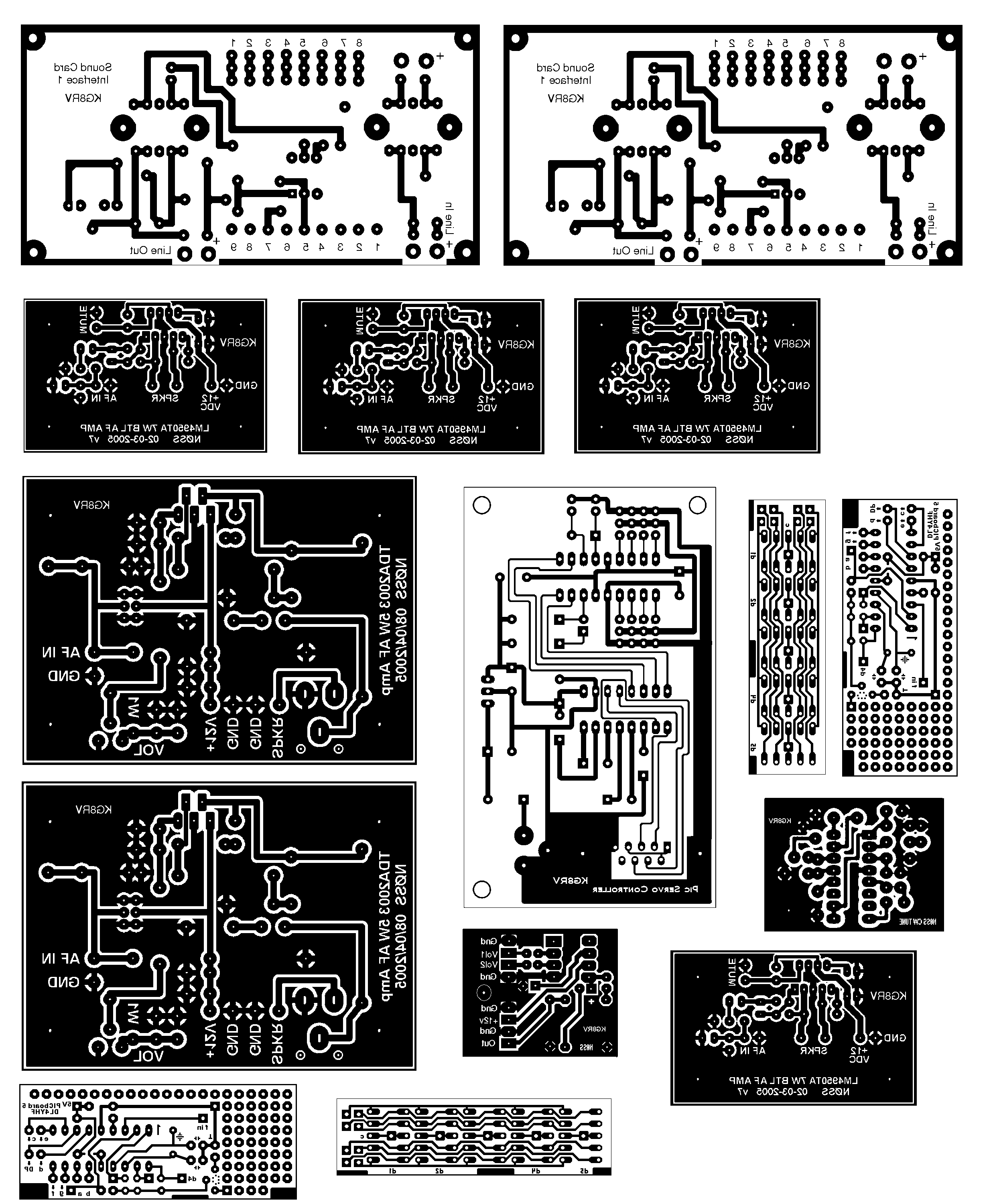
5-23-08
Circuit boards!
I etched some more circuit boards. A really
simple sound card interface, audio amps and
a couple cw indicators.
I made some boards for audio amps, frreq counter,
and line out for my k2.
![]()
5-9-08
K2SP Elecraft EC2 Speaker
I started work on my external loud speaker designed
by N0SS and I'll have info here as time goes on.
update:
6-03-08
Drilled holes for front speakers. got boards etched
for pcb audio amps. My brother talked me into adding
a woofer on the bottom to handle the lower tones when
used with a pc.
![]()
5-4-08
Simplex Repeater
I bought this thing from here. I got 1 of 2 beta units
and of course I tore it apart to see what was in it.
Very clean project and so far works pretty good.
The cable I got with it didn't work with my radio
so I made an adaptor to try things out until I get
a cable made that works and looks nice.
![]()
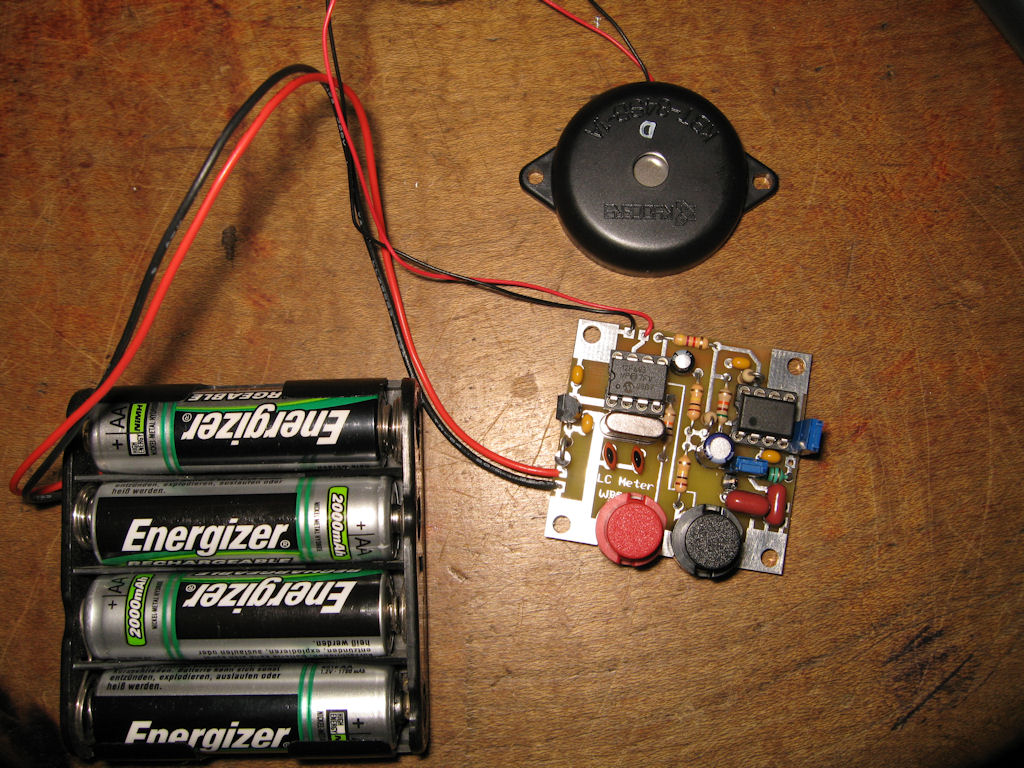
4-27-08
CW LC Meter
A kit I bought from here so I don't have to look up
numbers for capacitor/inductor sizes. Pictures to
follow.
![]()
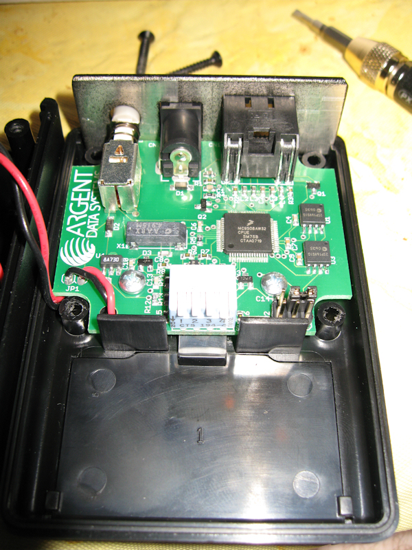
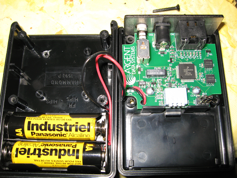
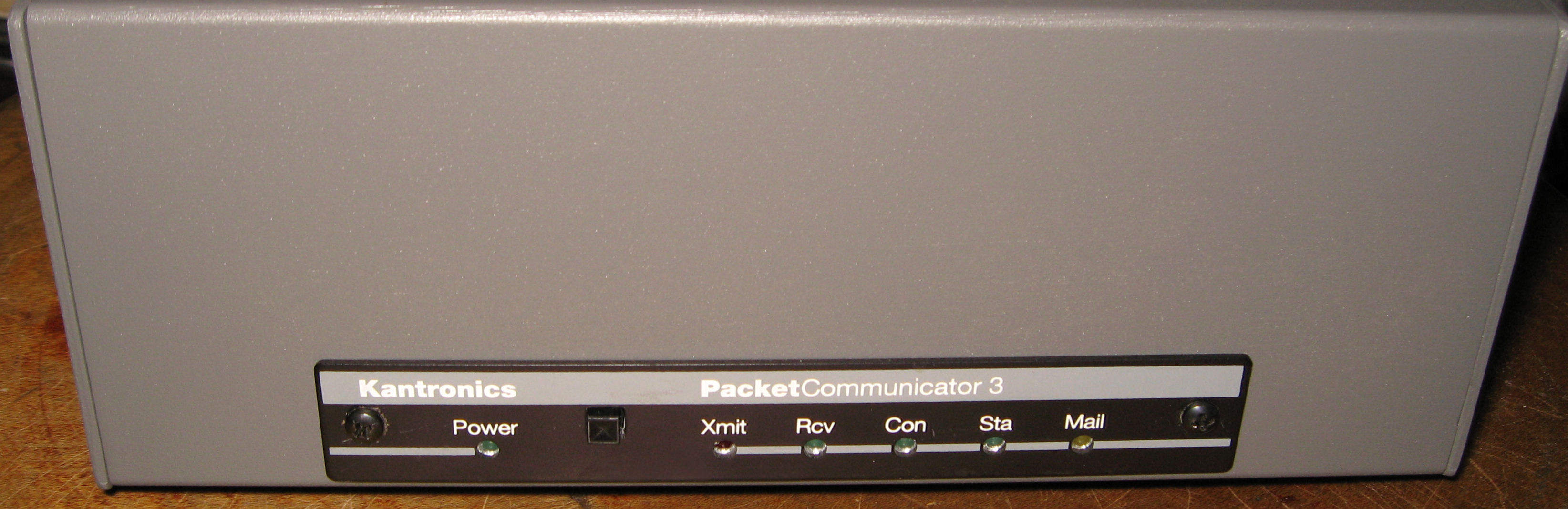
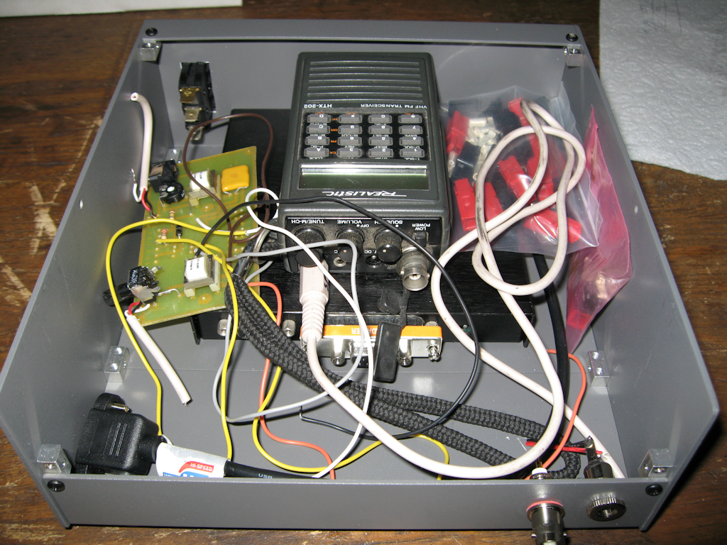
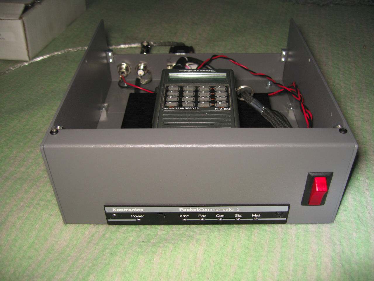
4-16-08
Elecraft EC2 packet station
I'm installing my Kantronics KPC-3 into an ec2 case
along with my HTX-202 from Radio Shack. I will also
be adding a sound card interface to the box as it is
similar in function. I got pics of the face of the station
but will upload later.
update:
6-29-08
Added power switch, power jack and antenna connection.
update:
4-11-09
I got this thing on the air so far. I still need to add the
sound card interface to the inside but here is the guts
so far.
![]()
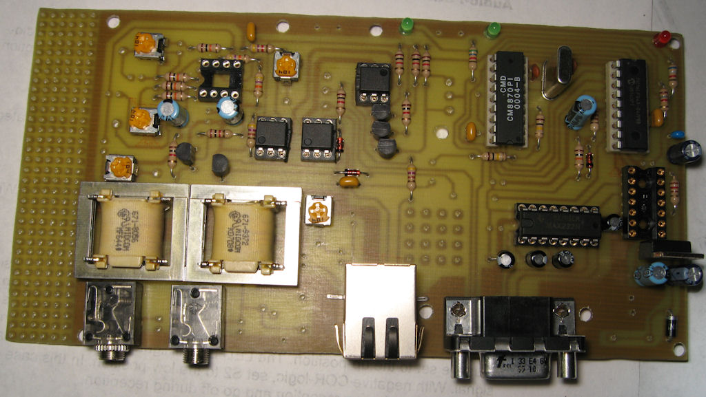
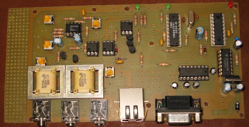
3-25-08
Echolink interface
After 2 weeks of work on a bitmap I could just print
out on Press-n-Peal to make my own circuit boards
I finally got started building the circuit. I found the info
from here which is open source and is also a pic project
and I like both so I decided to go with it. Too bad there were
no pics of a finished project on the site.
Now if I could only find my drill bits!
updated:
4-16-08
Transformers to Rob from Modem
update:
5-20-08
Here is a converted bitmap of the
one I used converted by someone
and emailed to me. converted from
the 21meg file down to under 1meg.
bitmap I used converted(<1meg)
![]()
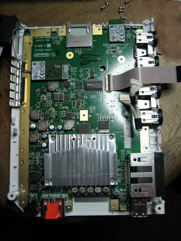
3-18-08
Wii Guts
I got a Wii to play bowling with my Mom and she is
actually playing. Not doing too bad even. Of course
any time I rip something apart with or without a reason
I usually take pictures and here they are.
![]()
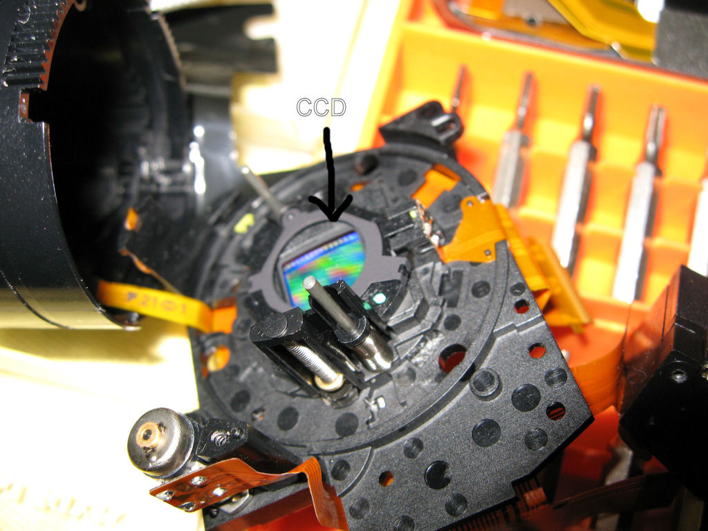
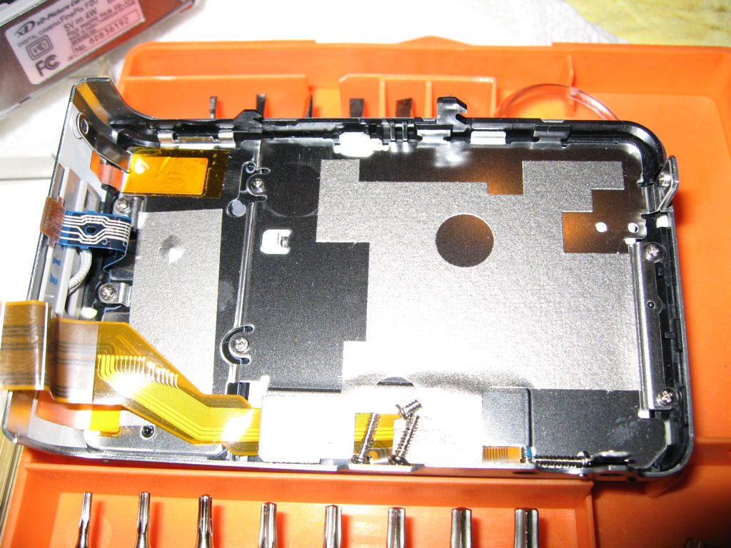
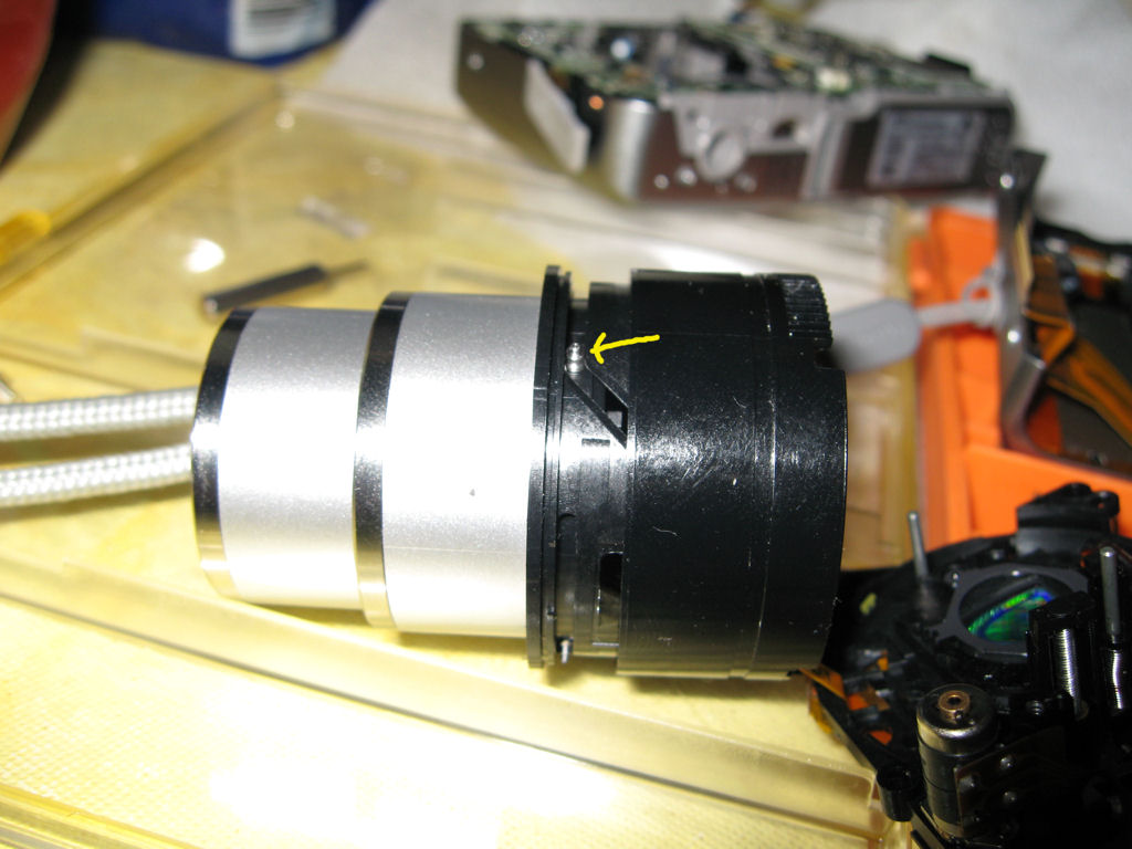
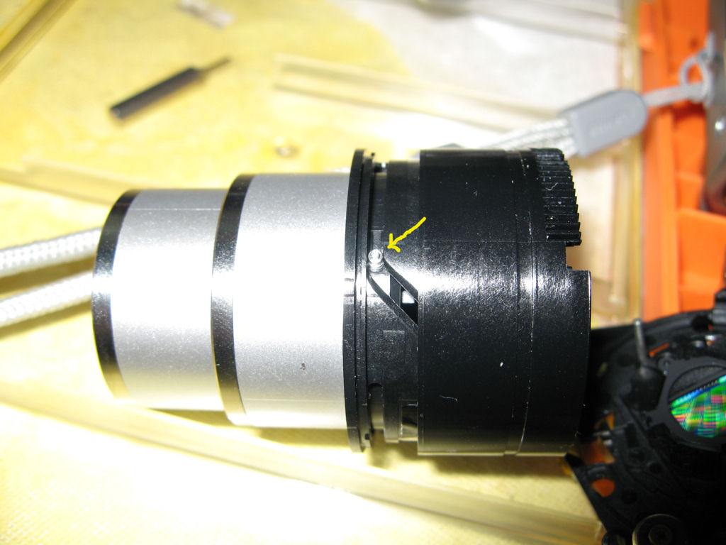
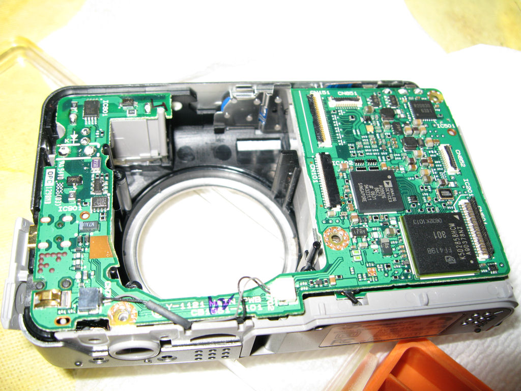
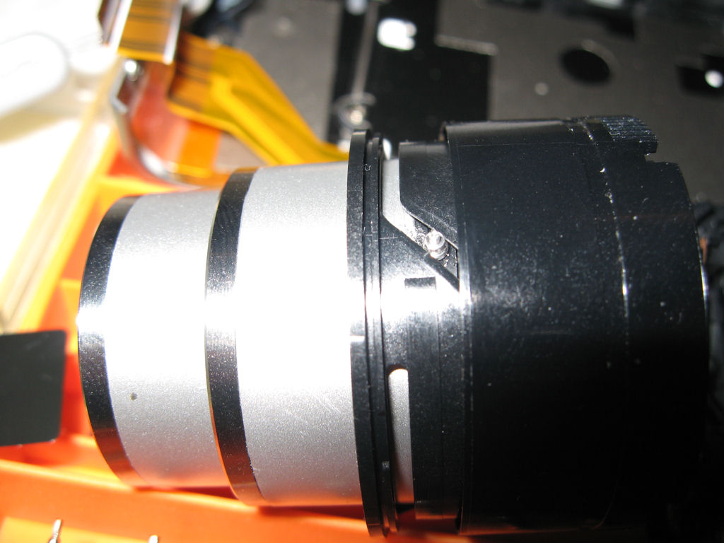
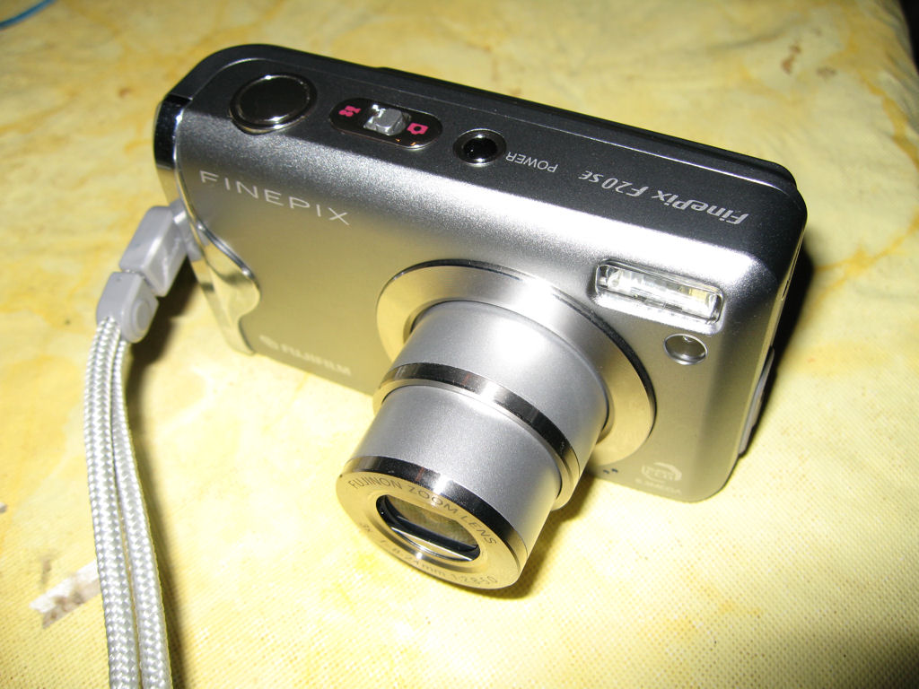
2-25-08
Digital Camera Repair
I got a Digital camera from my nephew's girlfriend
to see if I could fix it. It was dropped on its lens and
wouldn't open up.
![]()
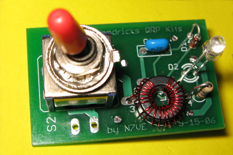
9-5-07
Led SWR Indicator for qrp
Made the 5w led qrp kit but haven't tested it yet.
I got it from here.
![]()
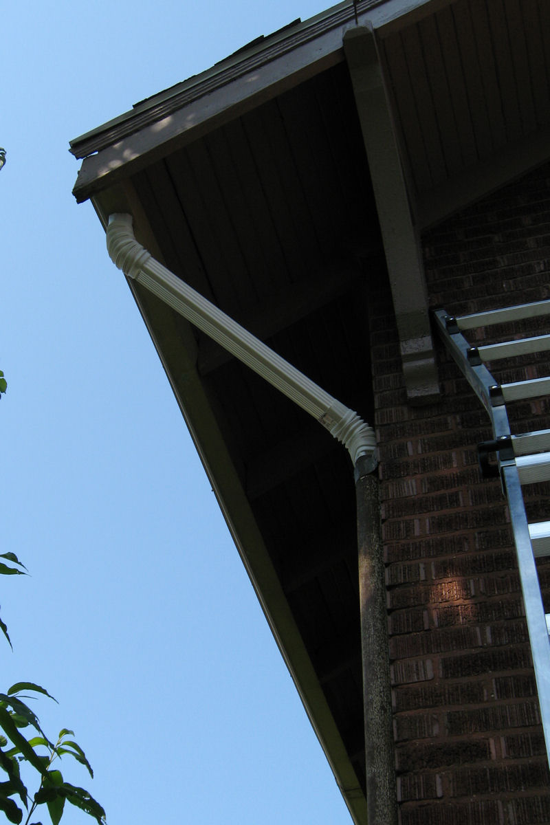
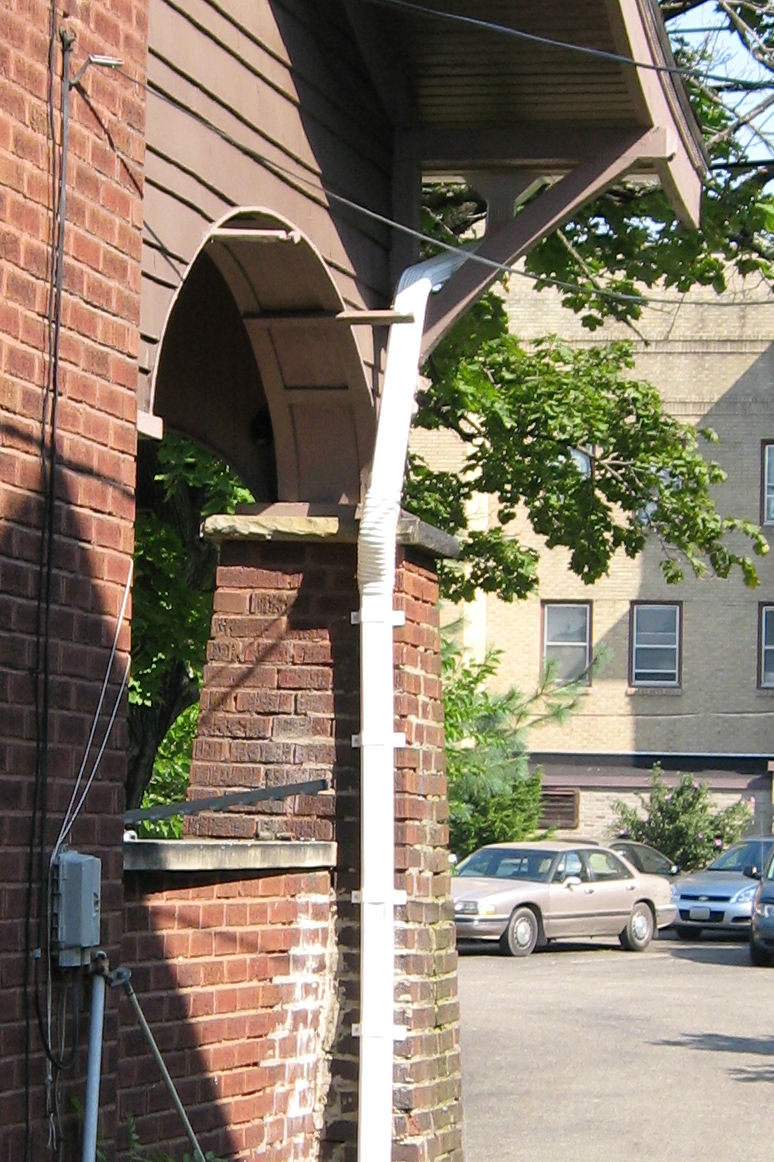
9-1-07
New Spouting and Down spout
Here are pics of my spouting repair work.
![]()
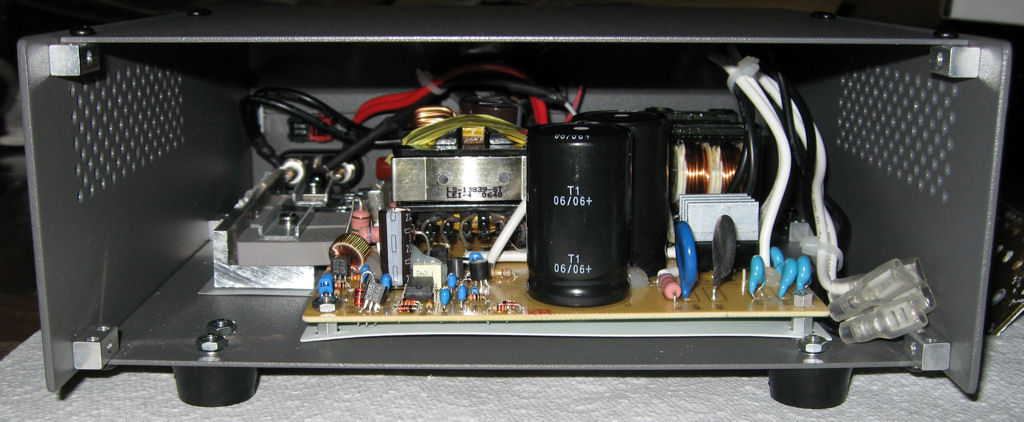
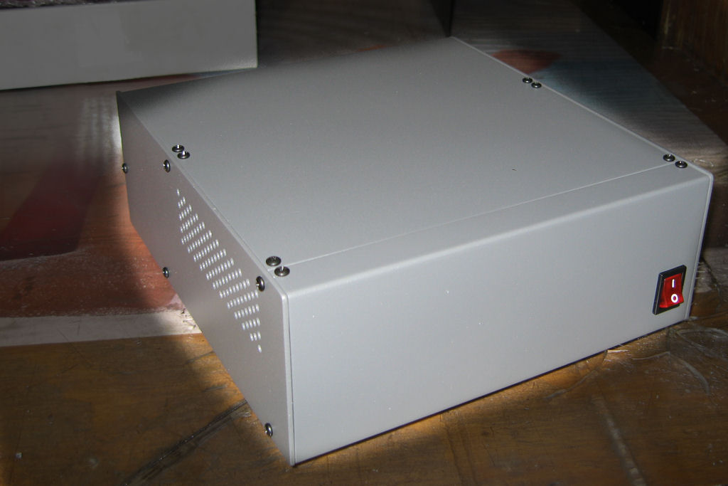
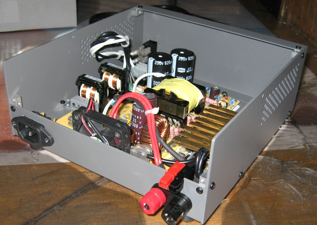
8-26-07
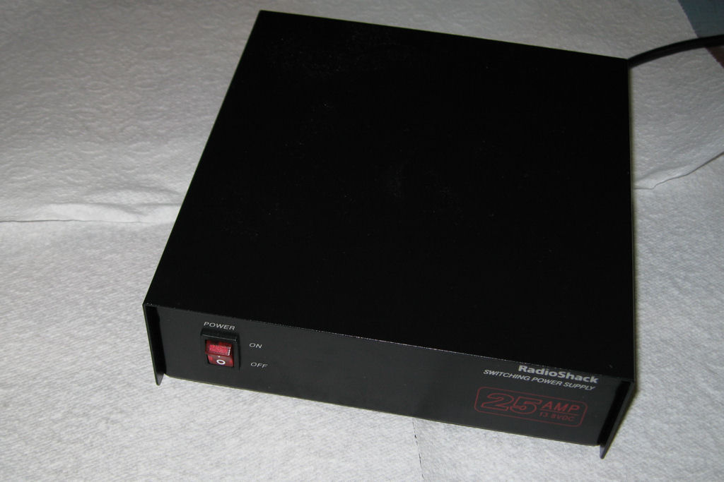
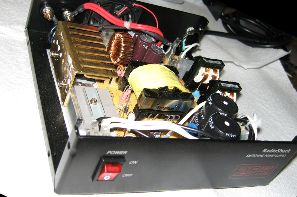
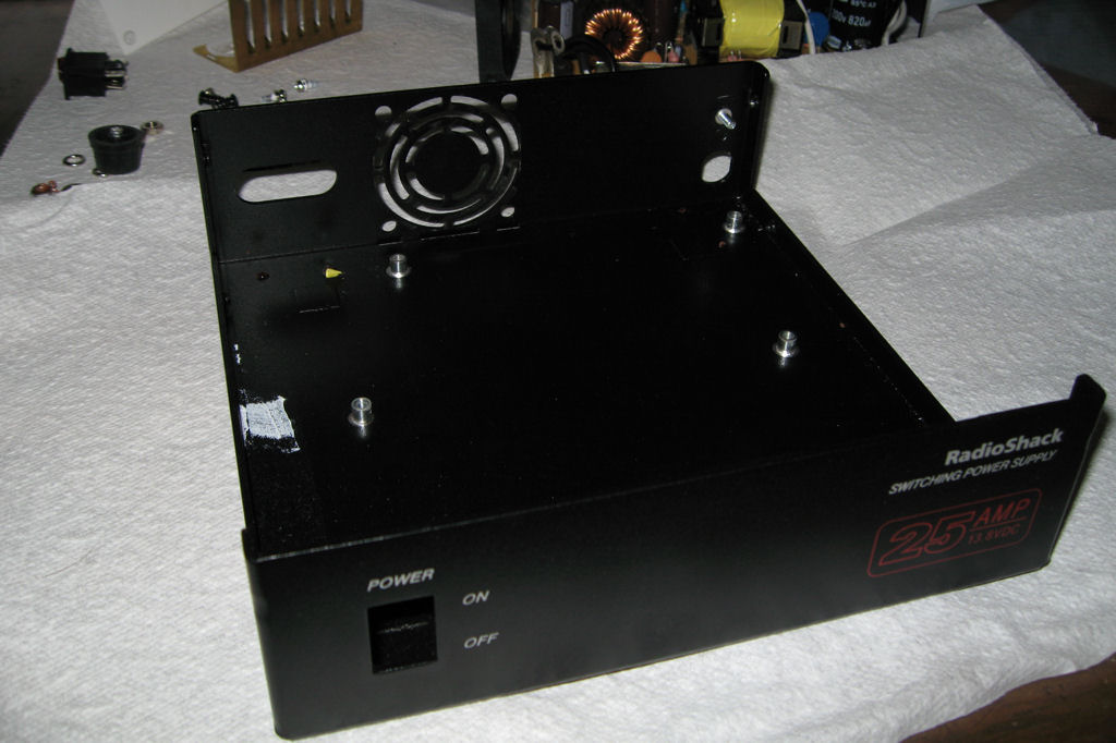
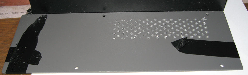
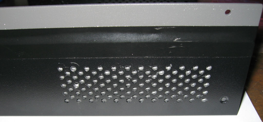
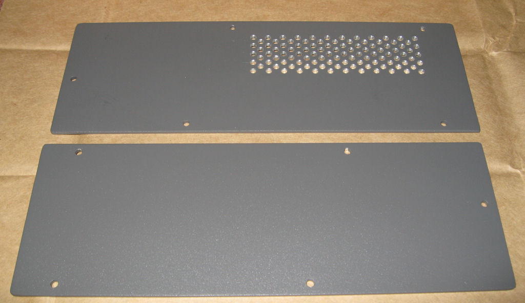
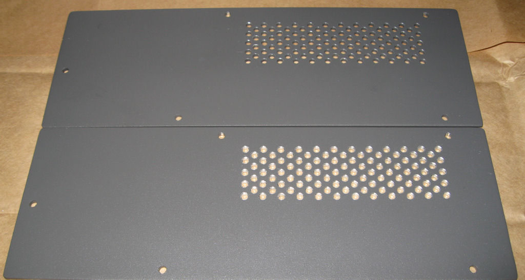
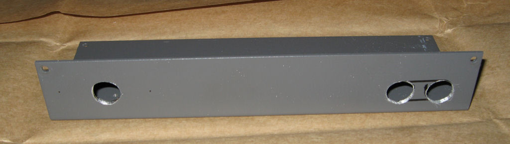
K2PSU - RS Power Supply in an EC2 case
I'm going to use the Radio Shack 25 amp switching power
supply to put in the EC2 case to power my K2 and my K2PC
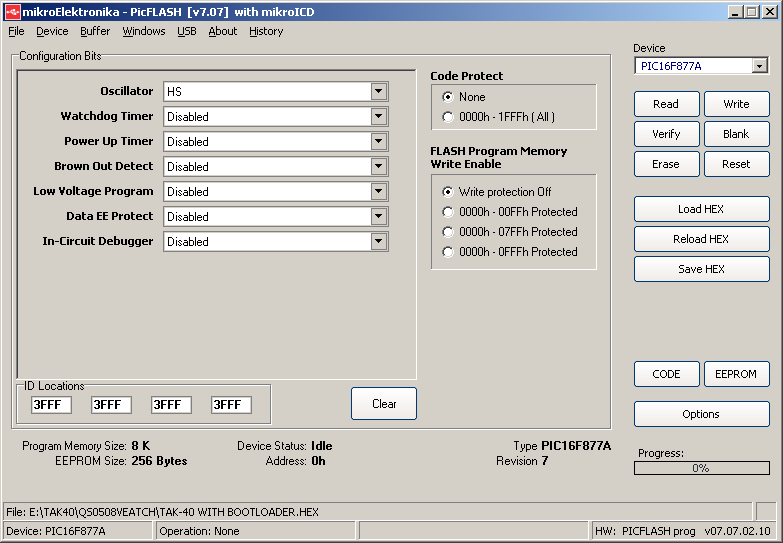
along with my Amp when I build it. I am starting on making
my own custom volt meter and amp meter using a pic
16f877a or 16f877 to run everything. I have the code done
to give me a top line and the bottom line will read the volts
and amps and maybe have a serial port to customize it.
update:
8-31-07
No luck on the current sensor giving me enough voltage
to drive my ADC. I tried a current sensor from TI but it
didn't work. I now ordered some free samples from
Maxim for a current amplifier so I'll try it when they
get here.
Update:
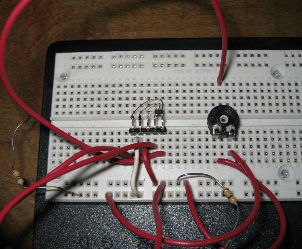
9-5-07
Good news, I got a current amplifier chip from Maxim
which is the Max4376. The 5 pin chip just takes 2 pins
for the sense wires, plus voltage, ground and the
output pin goes to the pic adc input. I chose the 100x
multiplier to get 0-50Amps from only the 50mV input
for the current meter....Here is my test circuit.
Update:
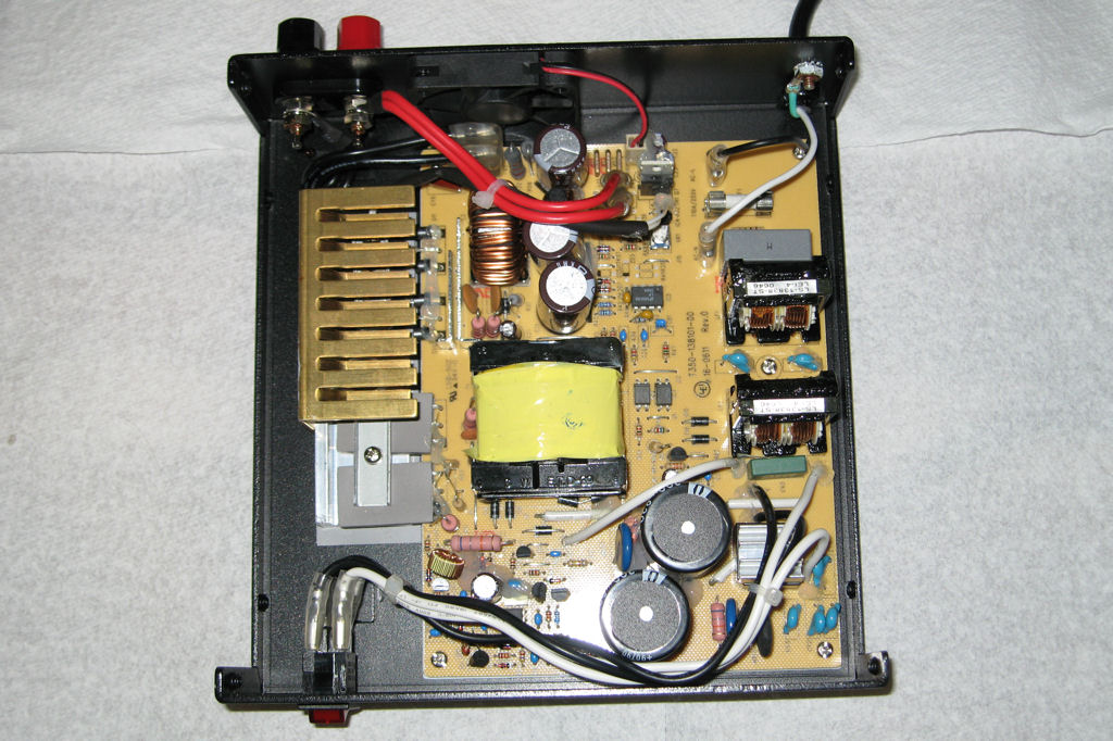
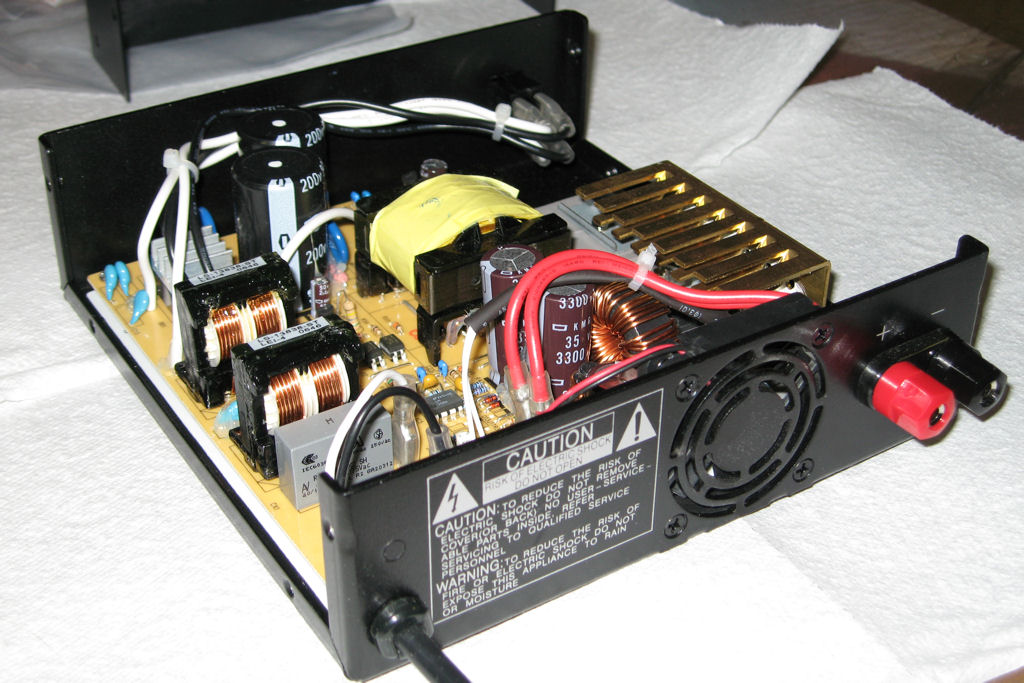
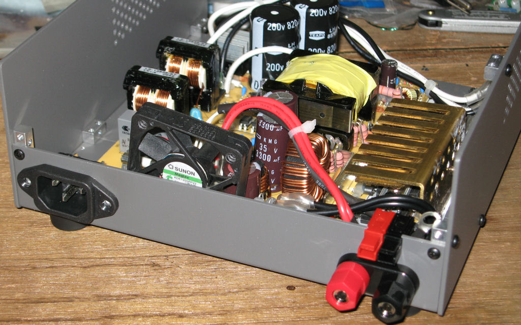
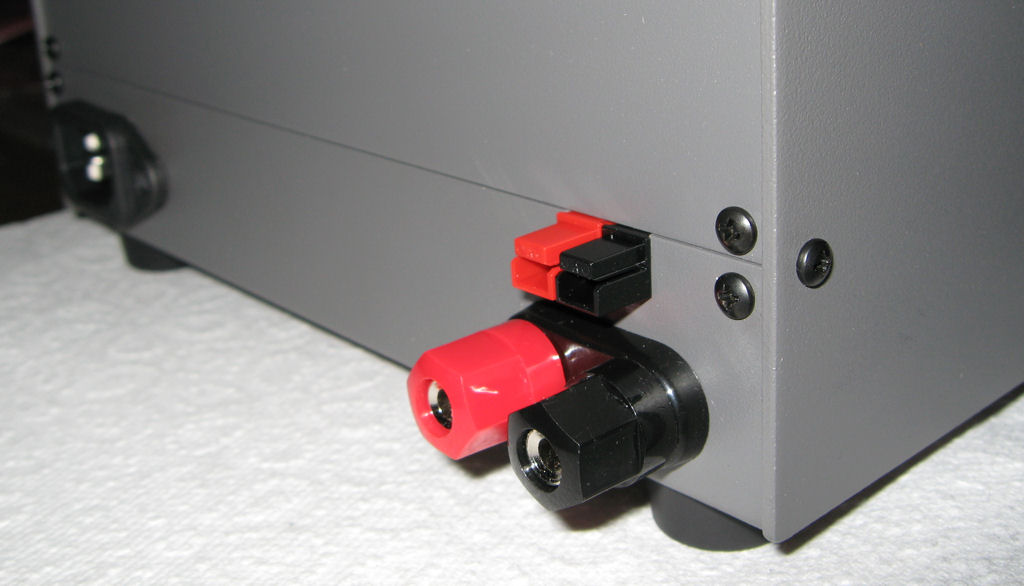
9-9-07
I got all the radioshack power supply parts installed
in the new case and so far it is coming out just fine.
Now all I have to do is finish my LCD meter
and get it installed along with a hole in the back
for the cooling fan.
update:
10-15-07
![]()
8-9-07
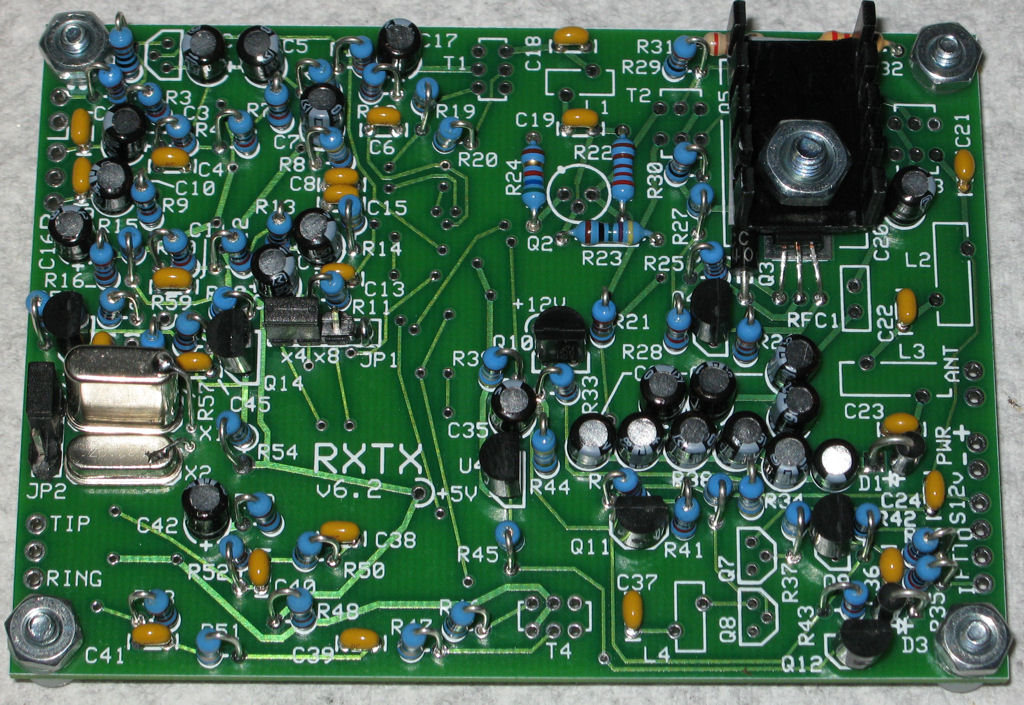
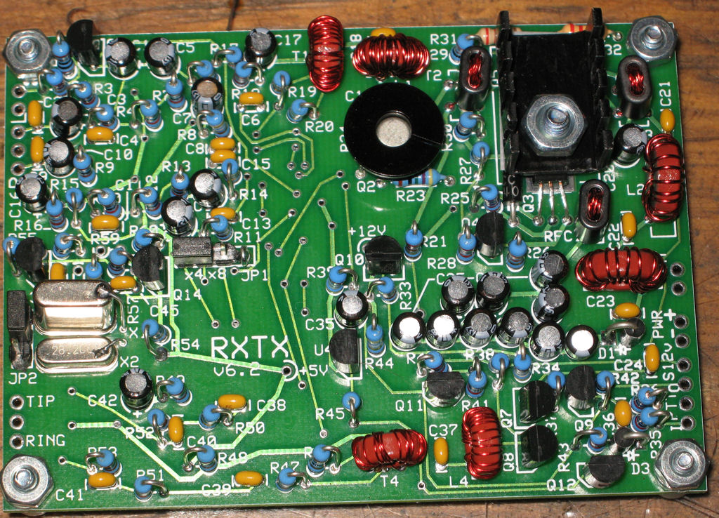
Softrock 6.2 Radio 40m/80m band
Here are pics of my softrock radio with is a 40/80 meter band
software defined radio. It uses the sound card of a computer
to work.
![]()
7-10-07
Laptop Fixed
Here is a laptop I fixed for a guy at work. Well, sort of fixed.
The laptop didn't seem to want to charge the battery when
it was on without smocking some components. Whatever
caused it to burn up in the first place was still bad, so I fixed
the MB so it could be used with the AC adaptor or battery
but didn't want to do both....New motherboard anyone?
Well, here are the photos.
![]()
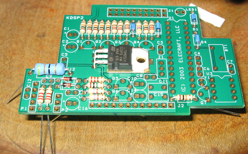
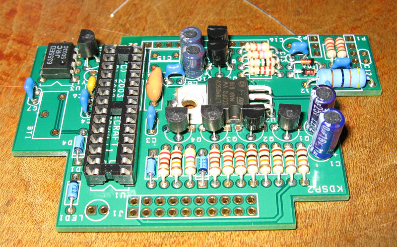
6-23-07
K2 DSP
Purchased my dsp for the k2 radio and here it is.
![]()
updated:
4-10-07
Hacked my ppc6700 phone cradle
I had to hack my cradle to get the generic power cable
to power the phone and to charge it as just using the
usb port didn't seem to give it enough power when the
battery was low. I found out that the power cable that
is supplied with the cradle normally has the negative
pin and the one right beside it shorted so the cradle
knows that it is plugged into power instead of usb.
It seems that the second negative pin turns on a
transistor which powers the led to show power is
applied. Works good now!
updated:
6-23-07
I did a second one and took pictures this time.
![]()
updated:
4-09-07
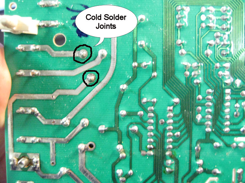
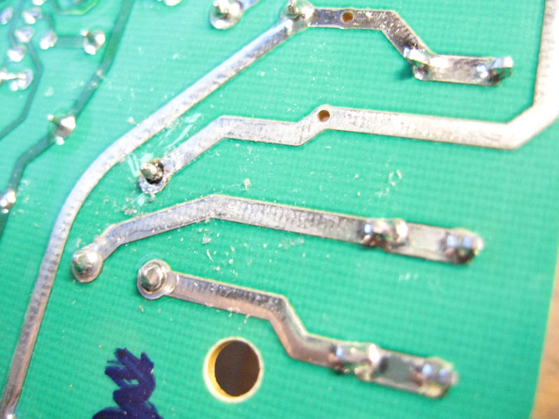
Tim's Furnace Control Board Repair
Here is a repair job request. Just found 2 cold solder joints
on the board. I removed both relays and resoldered them.
Now to install the board and test it!
![]()
updated:
1-17-07
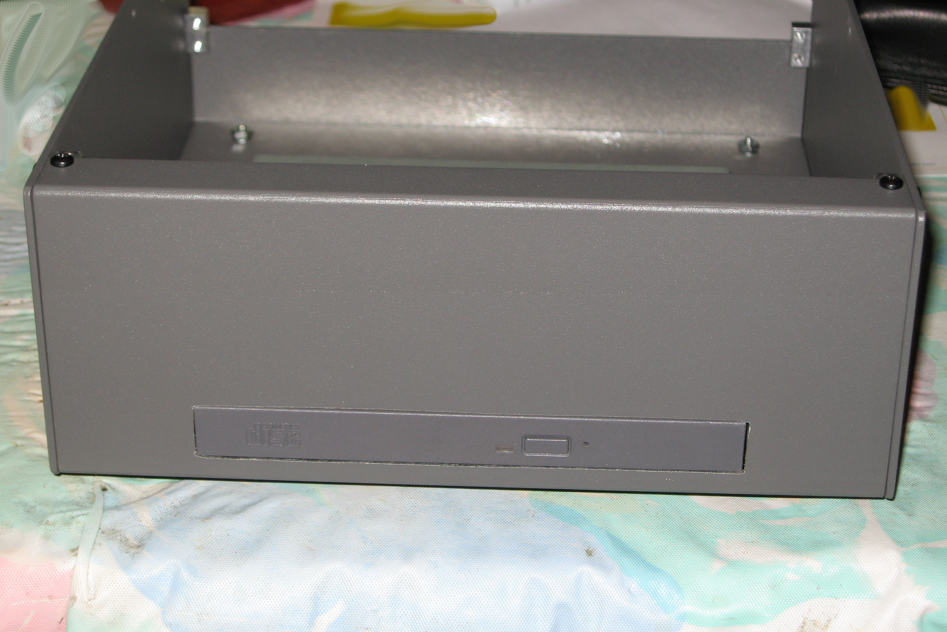
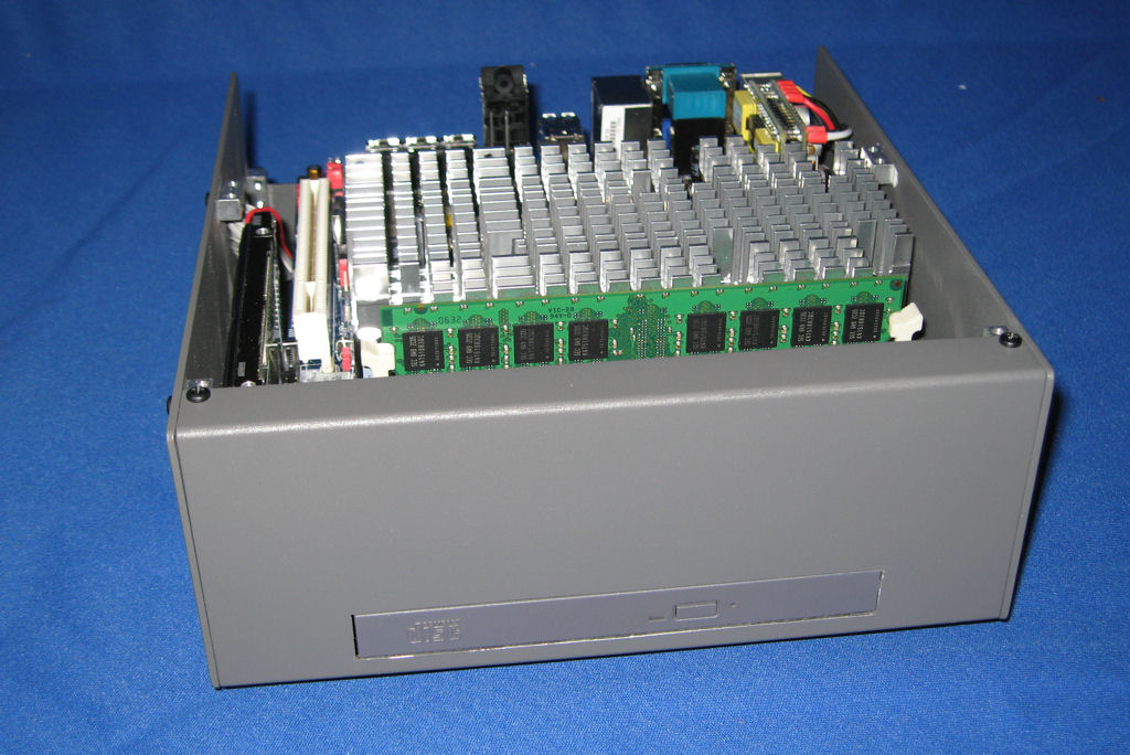
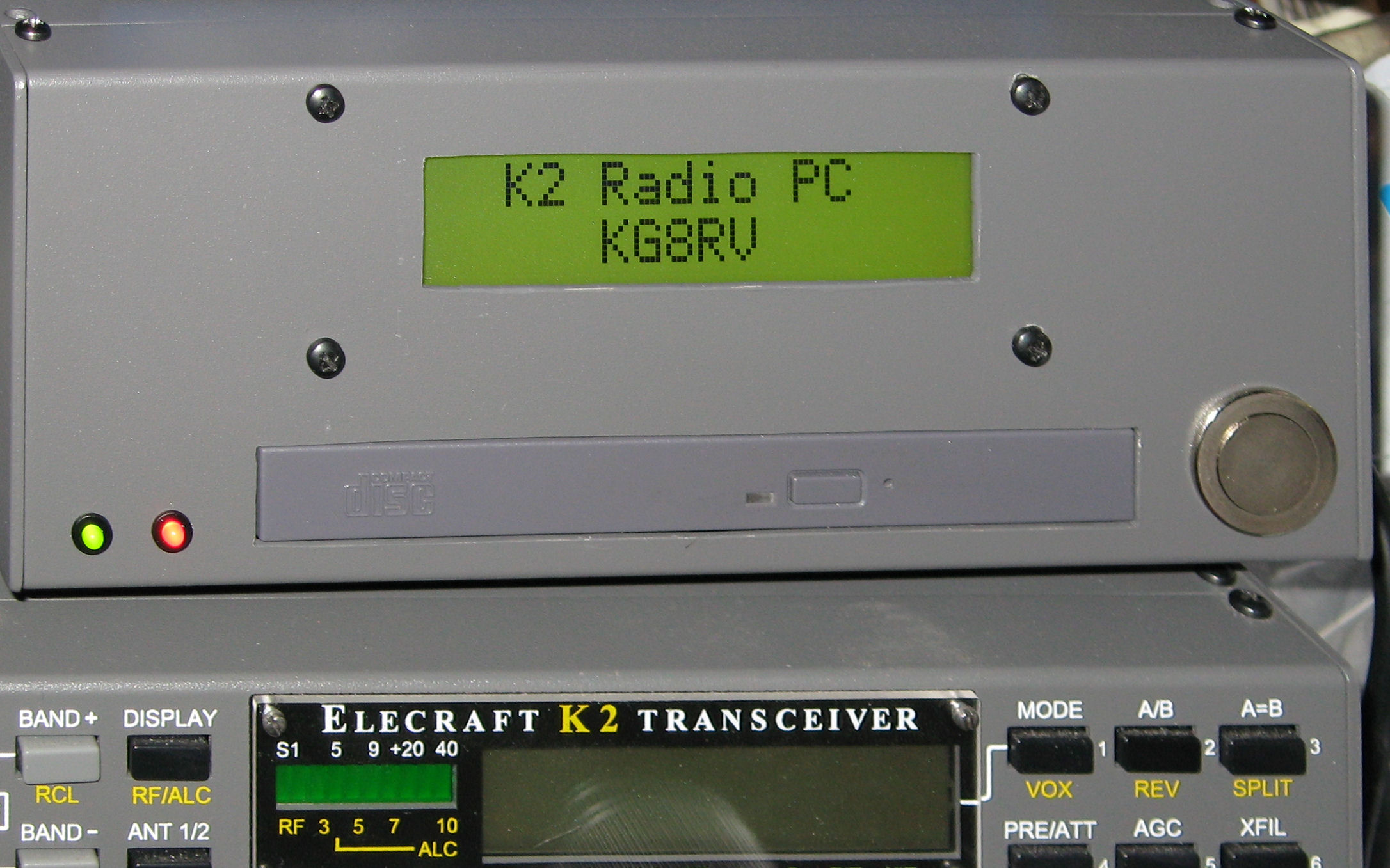
K2pc Computer in a K2 case
Here is a project I started to install a pc into an
Elecraft K2 EC2 radio case. I got the idea from a link
I found on their website except I'm installing a DVD
drive into the case or maybe a burner. Unfortunately
the MB was DOA right out of the box, so it went back
for replacement. Project on hold until it makes it back.
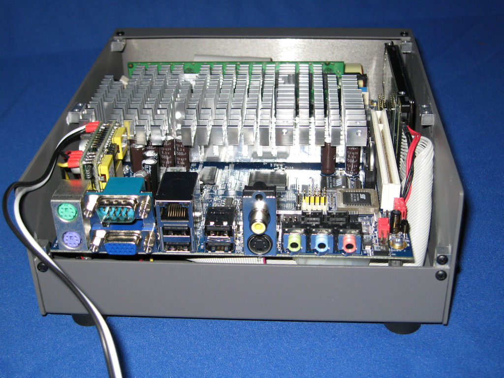
update: 2-2-07
I got a new motherboard as the one from newegg.com came
DOA so I ordered one from logicsupply.com and not having
much luck with the new one. I can boot everything up as
long as I have a POST code reader installed in the pci slot
which makes no sense, but here are some pics of what it
looks like so far. I have a 1.2 gig via cpu with 1gig of
ram and a 30 gig hard drive and even a cd drive which
will be a dvd drive (burner?) once everything is working.
I even have room to add a fan if needed but that defeats
the purpose of a fanless system. I also have a wireless
network card to install yet. And I might add a serial lcd
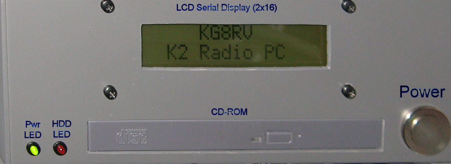
display to the front along with the leds and switches.
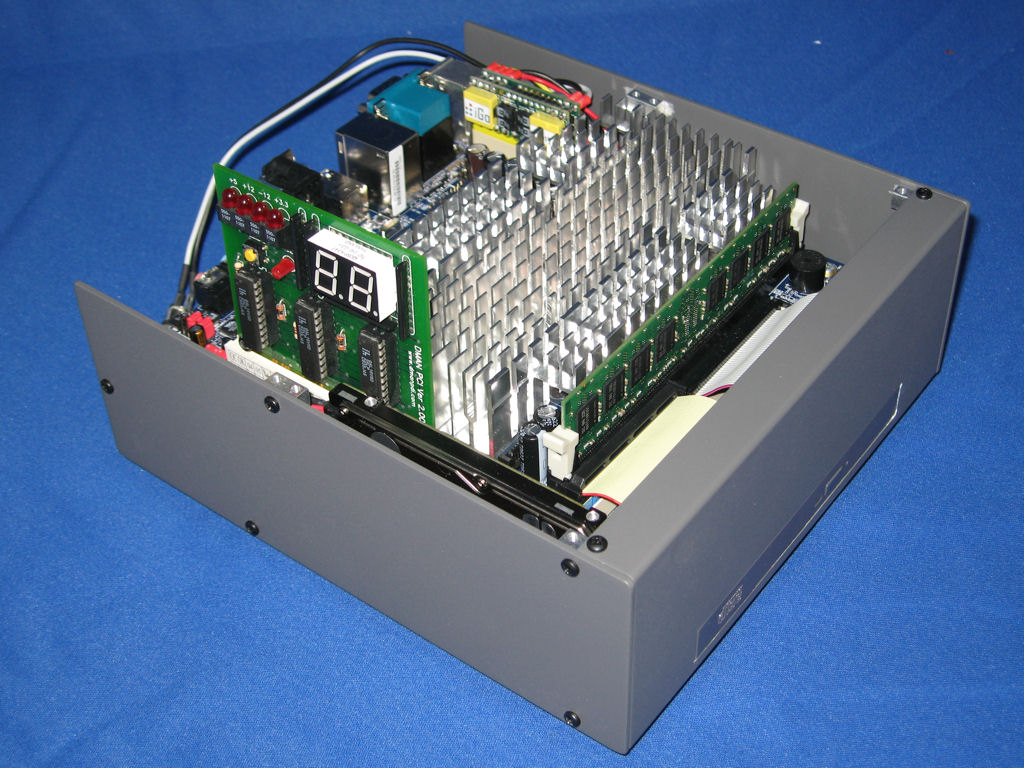
update: 3-4-07
I got my new board installed and added lights to the front
left side and got my wireless modem installed also.
update: 3-18-07
I got my lcd installed and working.
update: 4-08-07
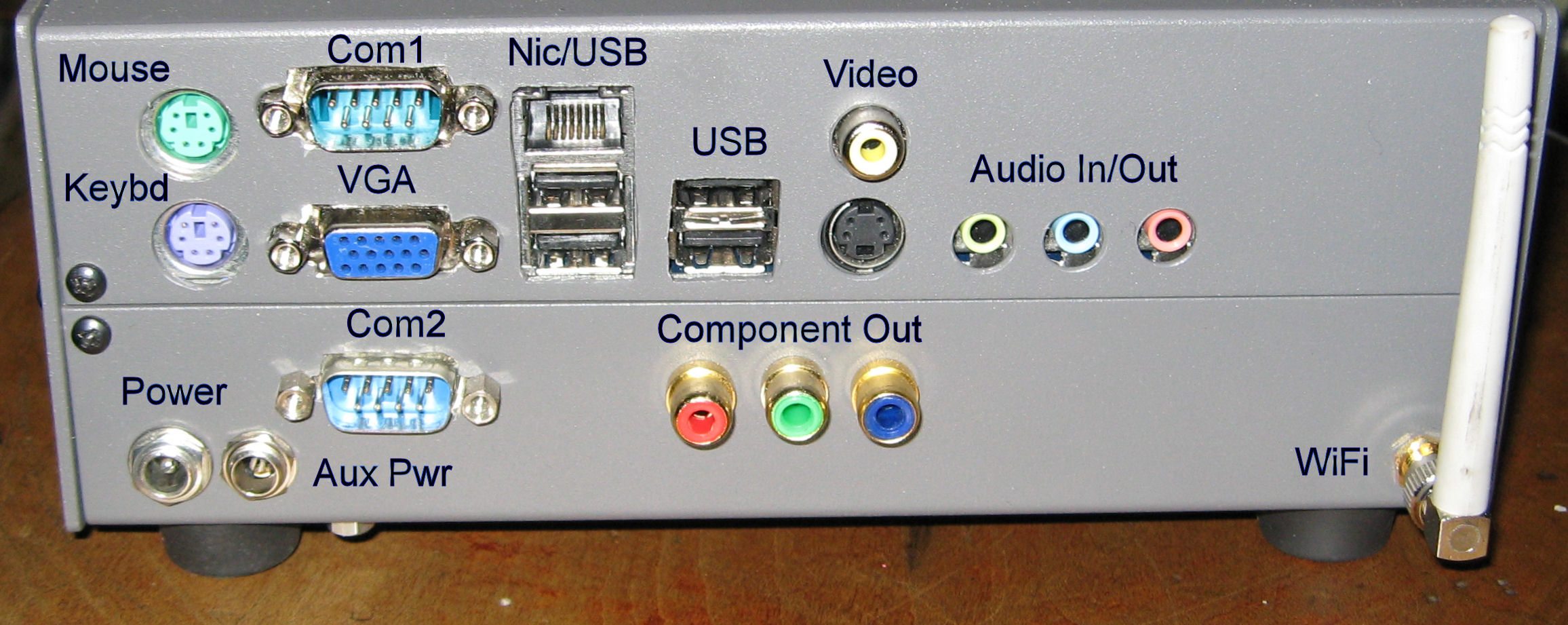
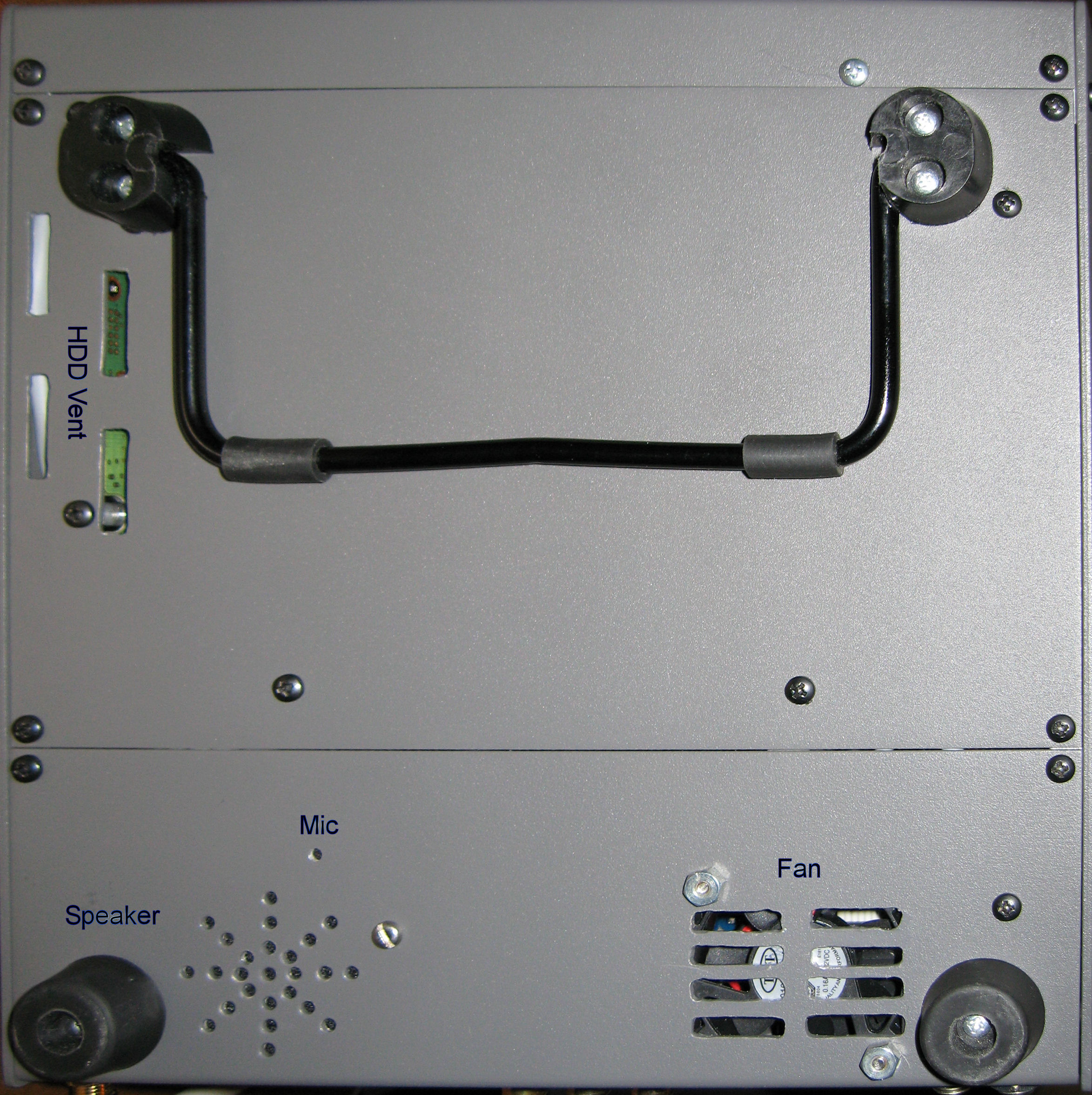
Now to install my RGB component output
jacks and front audio connector and internal
speaker. Also installed small fan to help
keep things cooler.
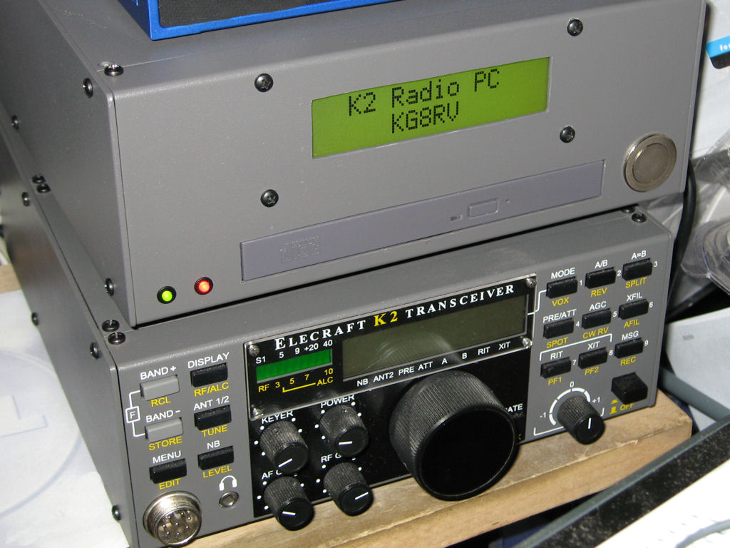
update: 4-20-07
I installed my component output jacks and still
need to do the audio. I decided to install the
audio jack in the back to disconnect the internal
speaker. Here are some new pics.
The component output looks really good now
that I found the right settings to make it work.
I have it hooked to my Sony 26" lcd widescreen
tv using 720p instead of the square screen that
the vga port was giving me.
Updated:
6-23-07
I added an IRDA port to the front of the case
after removing the led as it wasn't lined up
with the other 2 and I didn't feel it would look
as good.
![]()
updated:
4-19-06
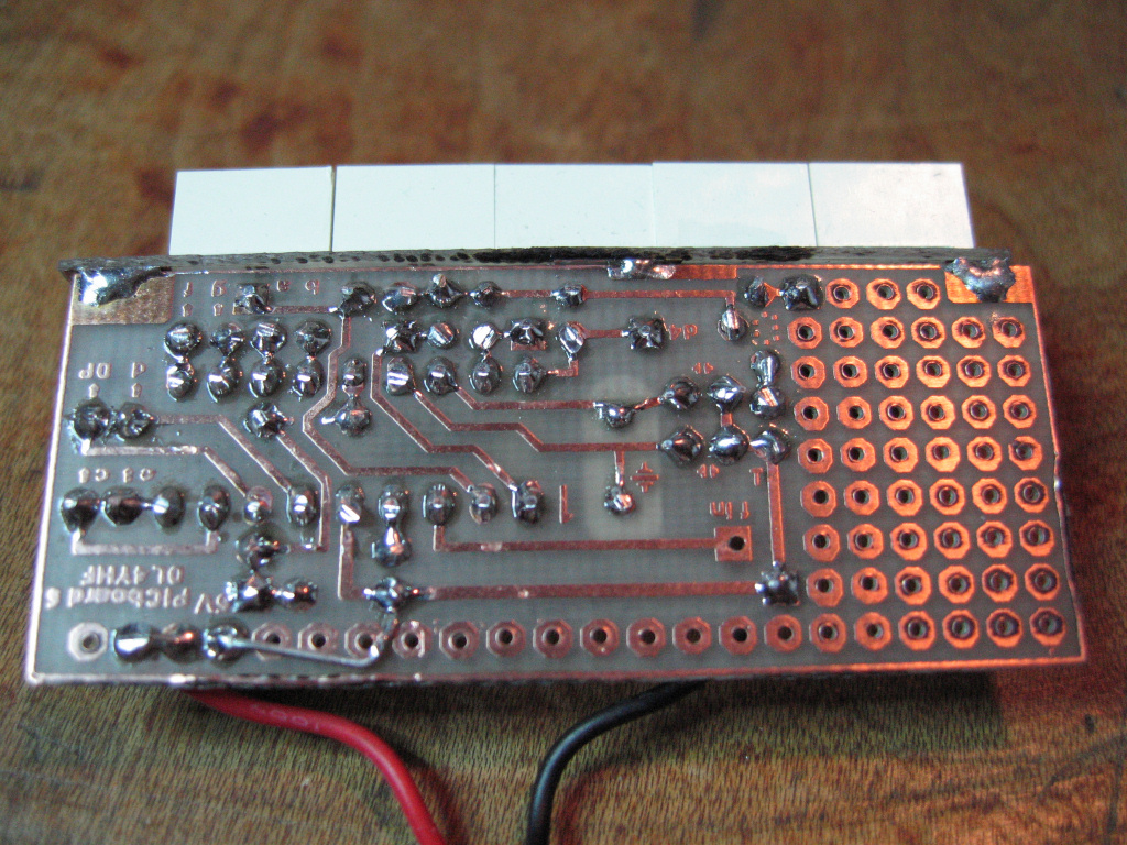
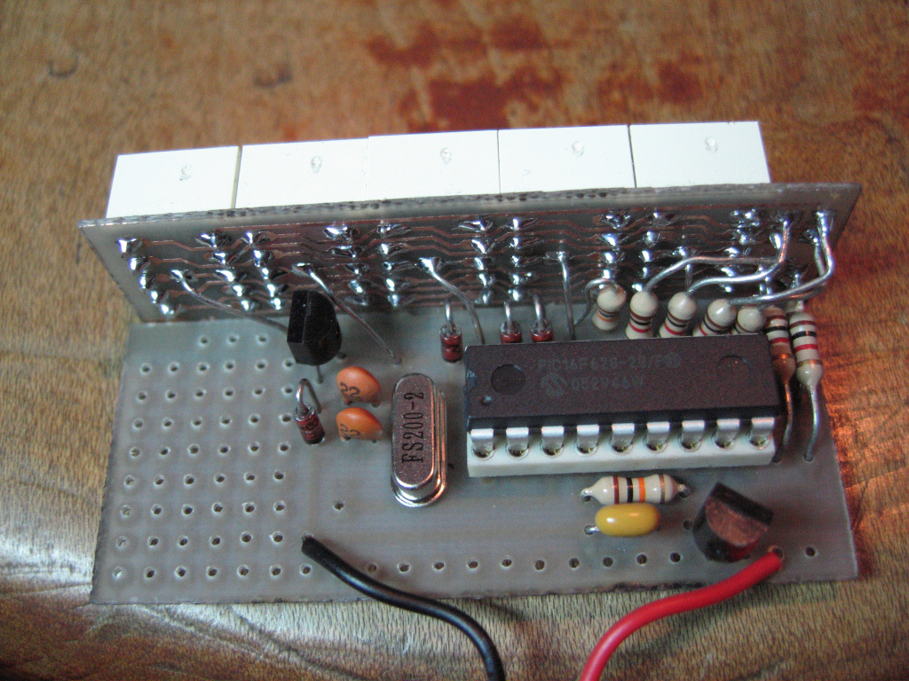
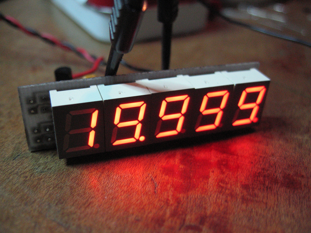
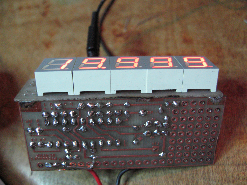
Freq. Counter Pic16f628
Here is pics of my frequency counter I made.
The info I got it from is at this link.
I etched the pc boards which I slightly modified
so I could solder the two boards together. Now
I need to install the circuit for the input so I can
have a high impedance input. I also need to put
it in a box, but here is what I have so far.
![]()
updated:
02-12-06
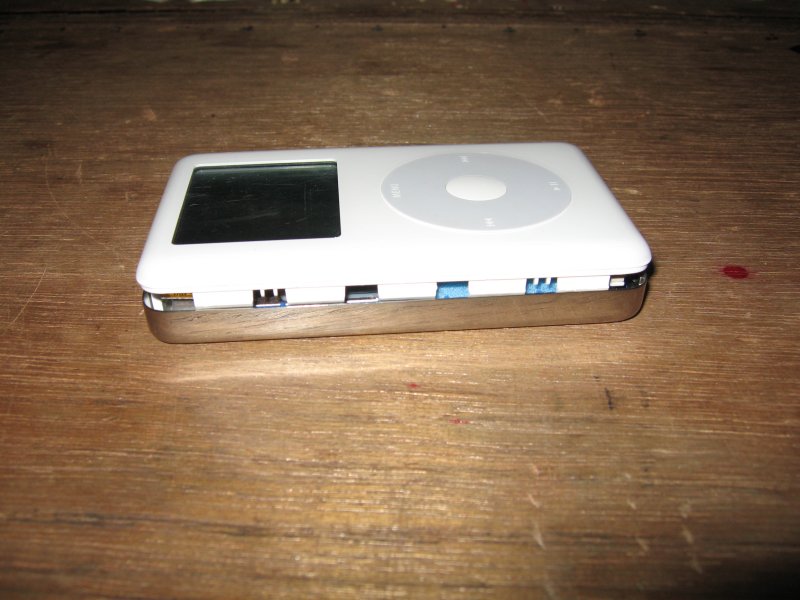
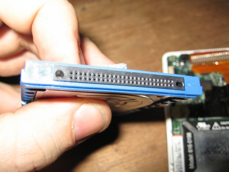
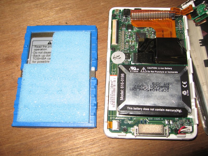
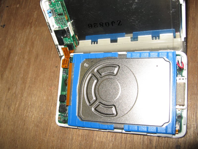
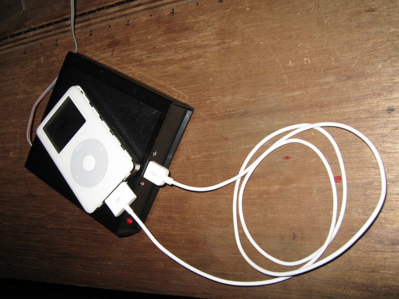
Ipod, Fix the Ipod!
Here is my attempt at fixing an Ipod. Not mine,
but something to do I guess. I have pictures of
the guts of the thing and what the drive inside
looks like. The battery is showing on one of them
too. I'm also charging it up with a battery circuit
that I added a usb port to so I can charge usb
devices with it.
![]()
updated:
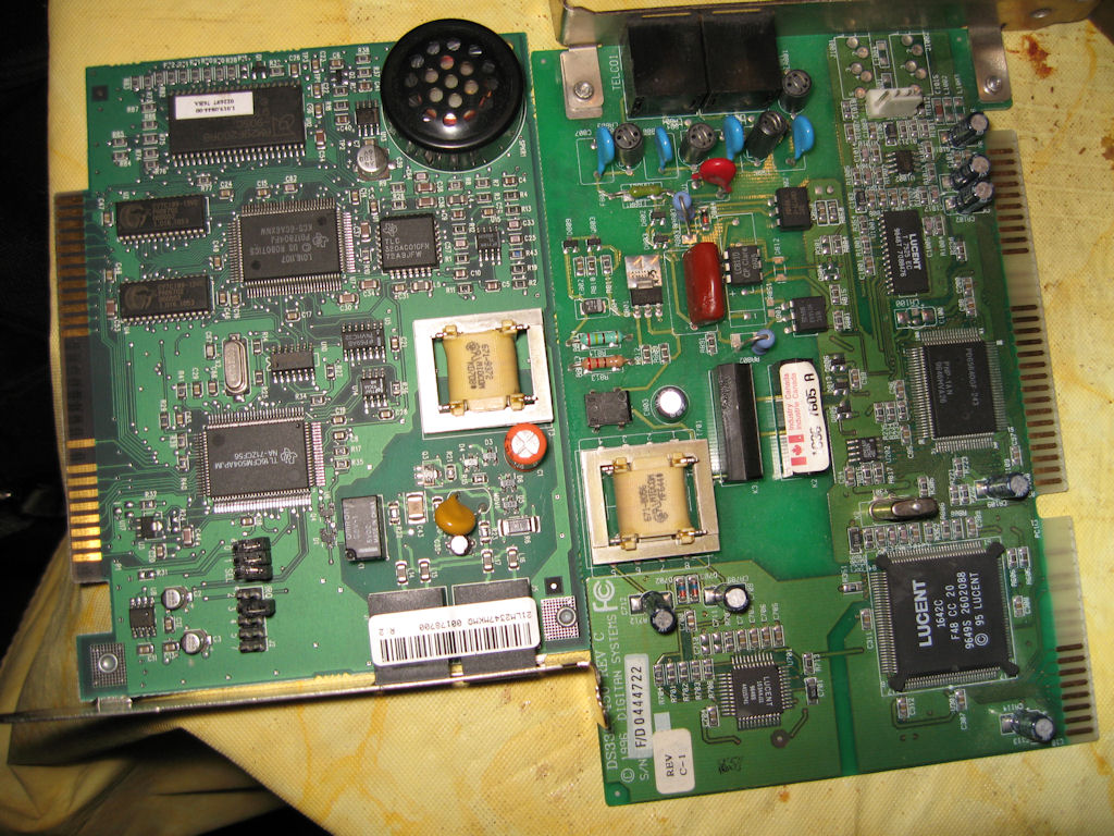
2-07-06
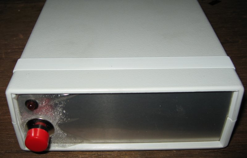
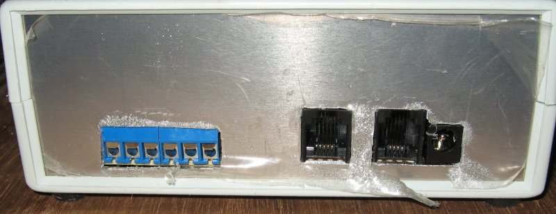
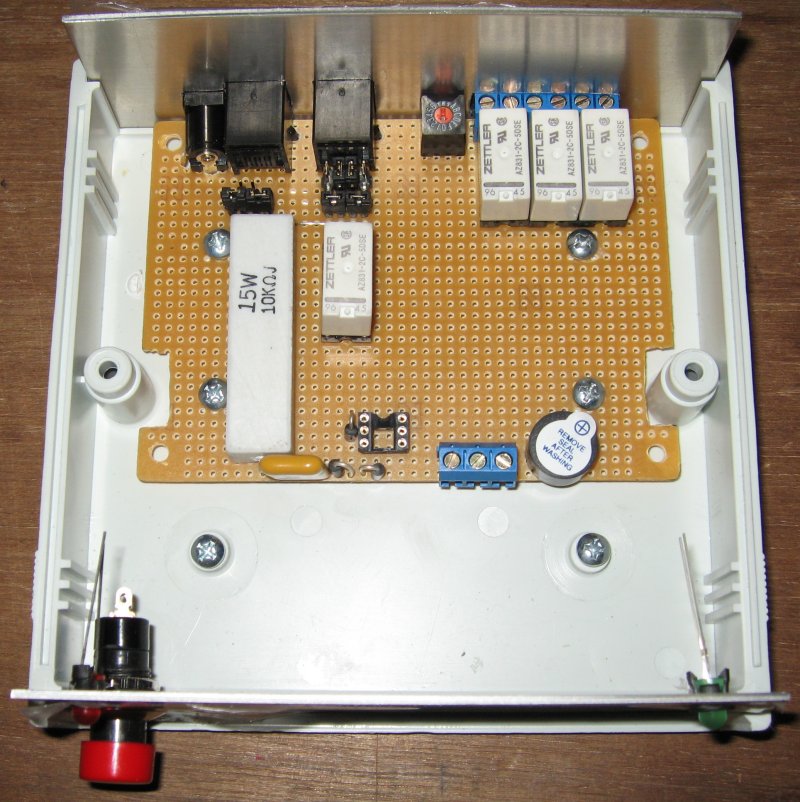
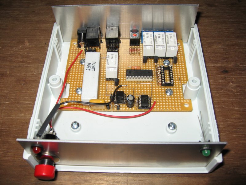
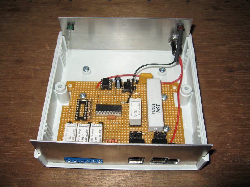
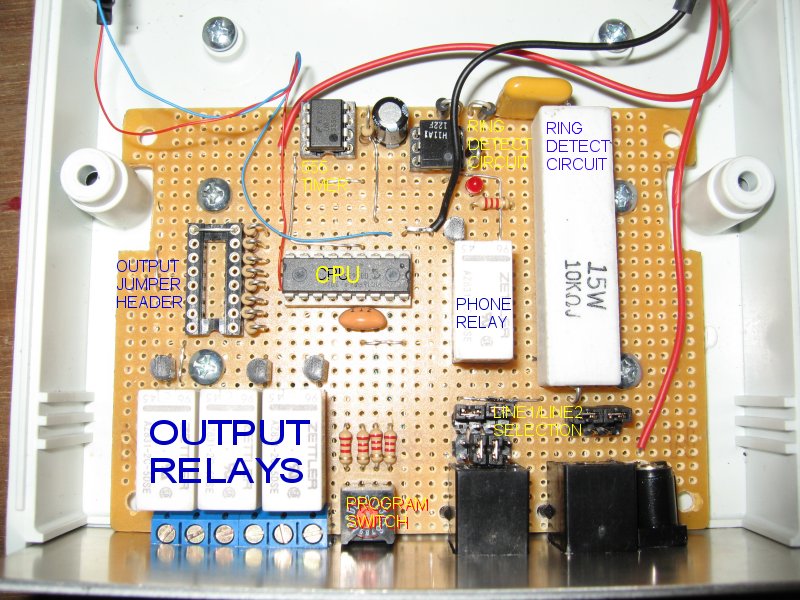
Telephone monitor
This circuit monitors my phone line and allows
me to turn on devices or enable my phone if
I turn it off to sleep but still allows those who know
me to still get a hold of me when needed. Without
all the telemarketers bothering me. This is just the
start of the project.
update:
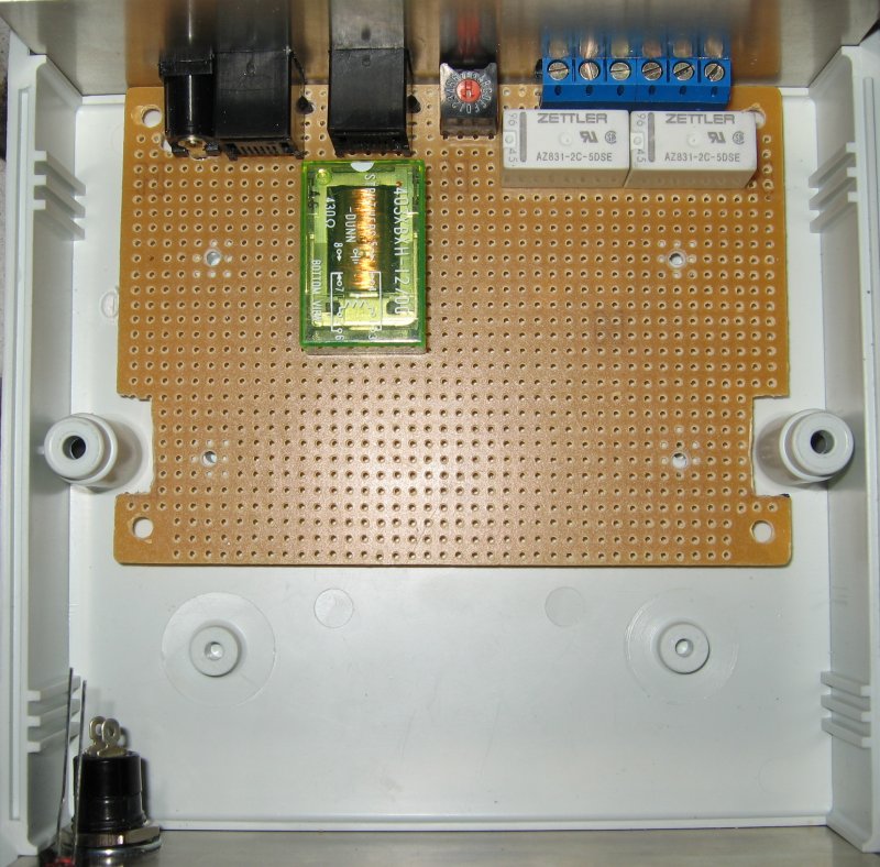
2-15-06
I added more components and tested the ring detector.
Added the rest of the circuit and did some preliminary
tests to make sure the substitute parts work ok and to
make sure things are working as predicted.
so far so good.
original designer of this circuit and info can be found here.
Of course I changed things to suit me and my needs.
update:
2-17-06
I finished the circuit, tested it on my phone line and
all works just fine. Now I can disable the phone when
I don't want bothered or am sleeping and those with the
right code can enable my phone, wake me up or just
bother me if it is important enough.
![]()
updated:
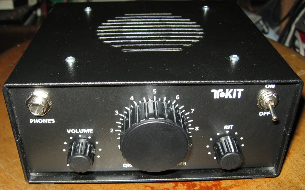
11-07-05
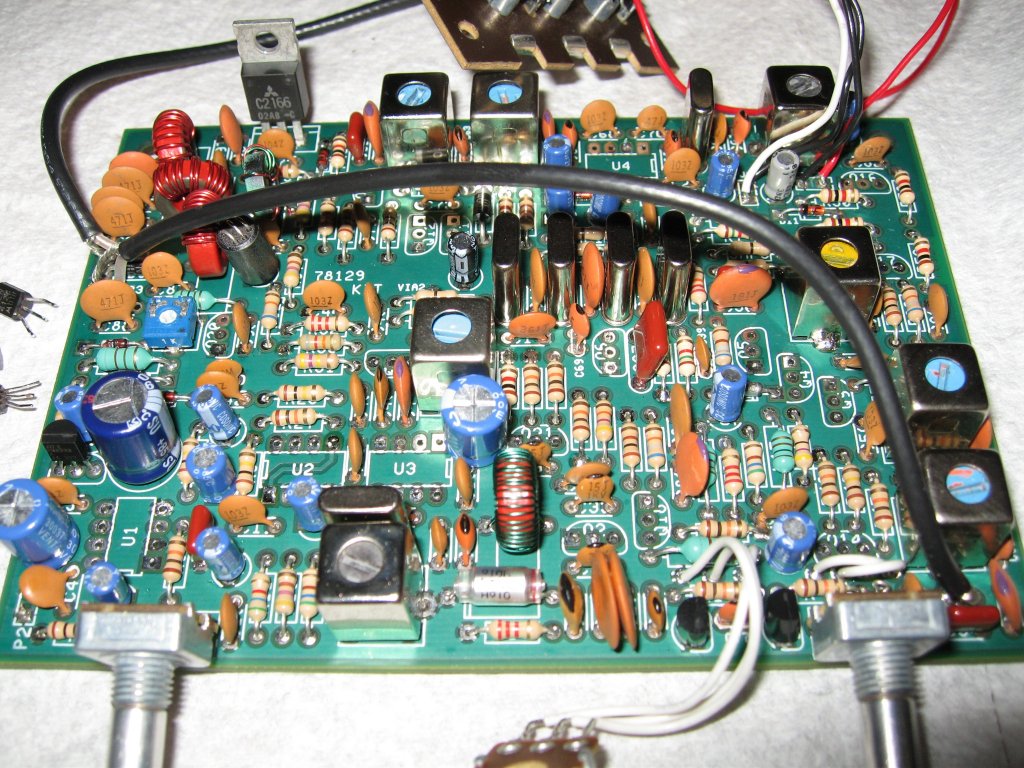
Ten-Tec QRP Radio Kit
This is a radio kit I'm doing for a friend. I only have
the latest pic so far where I'm actually getting some
noise out of the unit. I hooked the antenna up to my
other project which is an HF noise source where I
etched my own pc board and it all worked pretty
well so far.
update:
12-13-05
After finishing the parts installation, I thought
I'd hook it up to some power and listen to a
radio station or so. I actually found one but
unfortunately it was the tail end of the QSO.
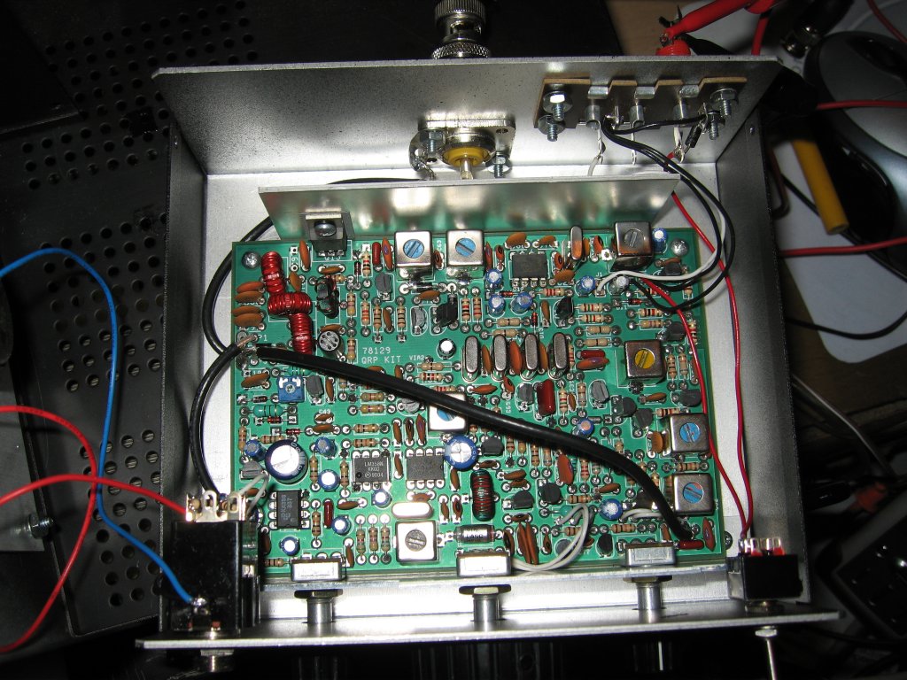
I haven't messed with it much after this other
than setting up the offset for tx and making
a few adjustments. Still need to work out
the issue of no side tone which might be
the wrong part as the book called for 1 and
the actual one was another story. Here
is a pic of the somewhat final radio with
all my test leads hooked up.
Additional Photos
update:
1-23-06
Oh I finally got the side tone working. Wasn't
anything serious. I found I just forgot to adjust
the tuning can so the 7mhz oscillator wasn't
doing much until I moved the core in. Now for
final tune-up and setup.
update:
1-24-06
OOOOhhhhhh NNNOoooooo!!!
I learned a very hard lesson.....
don't talk on phone when setting up a radio!!!
I hooked up the radio backwards on my last
test...heard a loud pop! then I found a
transistor with the head blown off of it.
I think it fried the audio amp as it makes
strange noises now...I just figured I'd change
all the iffy components at a cost of about $3-5
plus shipping and tax I guess. So I think I'm
going to add a diode protection circuit to the
radio so it wont happen again....that and stay
off the phone while working on stuff!!
update:
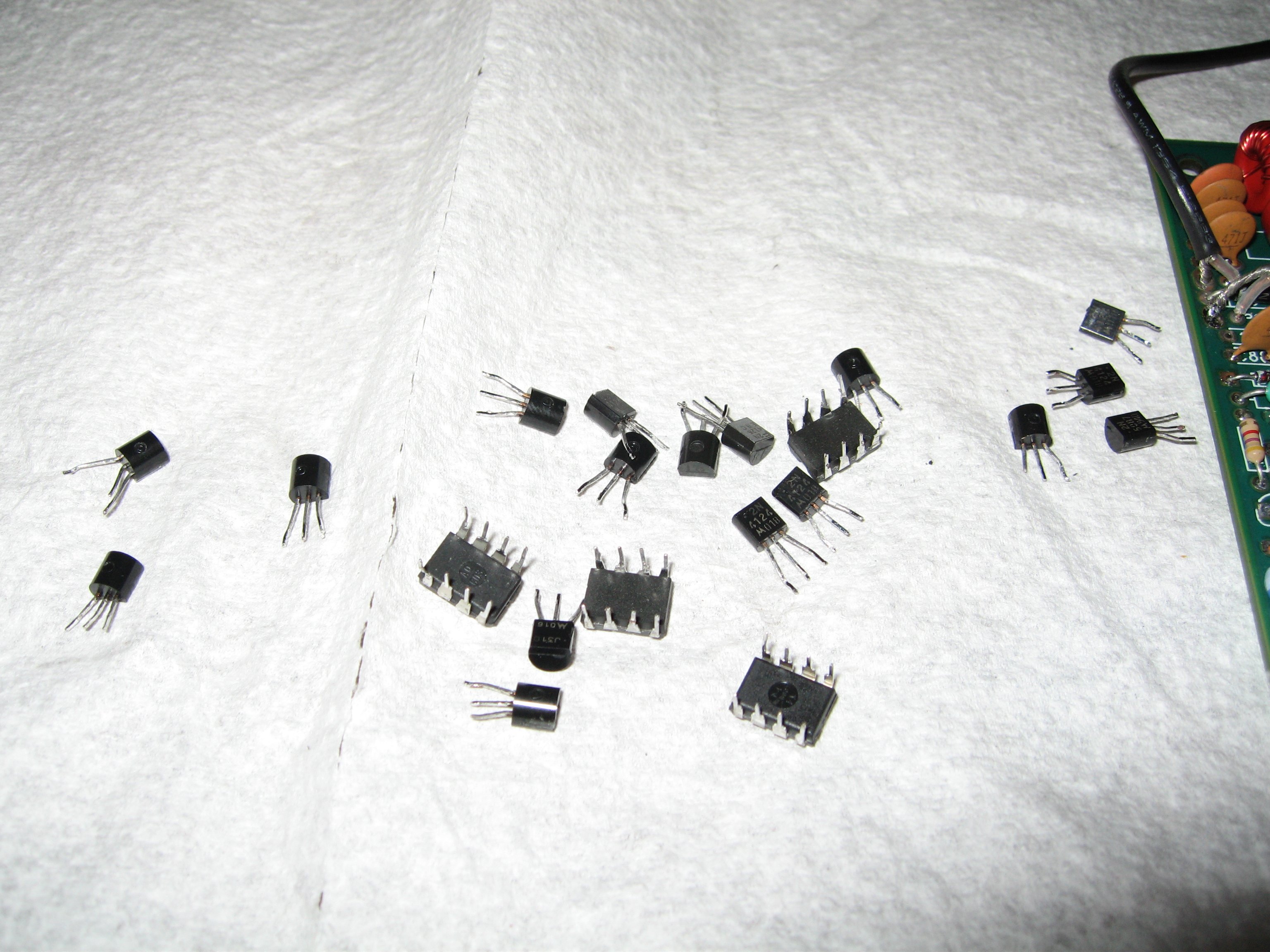
1-28-06
Repairs have commenced. I got all
the transistors and IC's removed and
ready for the new ones when they
get here.
update:
1-29-06
I got repair parts installed and all works
except the only part I didn't find which is
the final amp. I ended up finding it at
halted.com so other than more expense,
I'm on my way to finishing this little radio.
update:
2-8-06
I got repairs done and radio all tuned up.
The radio was receiving from 7.0502 to
7.1217 and after putting the wax on the
coil to keep it from moving it now goes
from 7.0572 to 7.1280 and all seems fine.
![]()
updated:
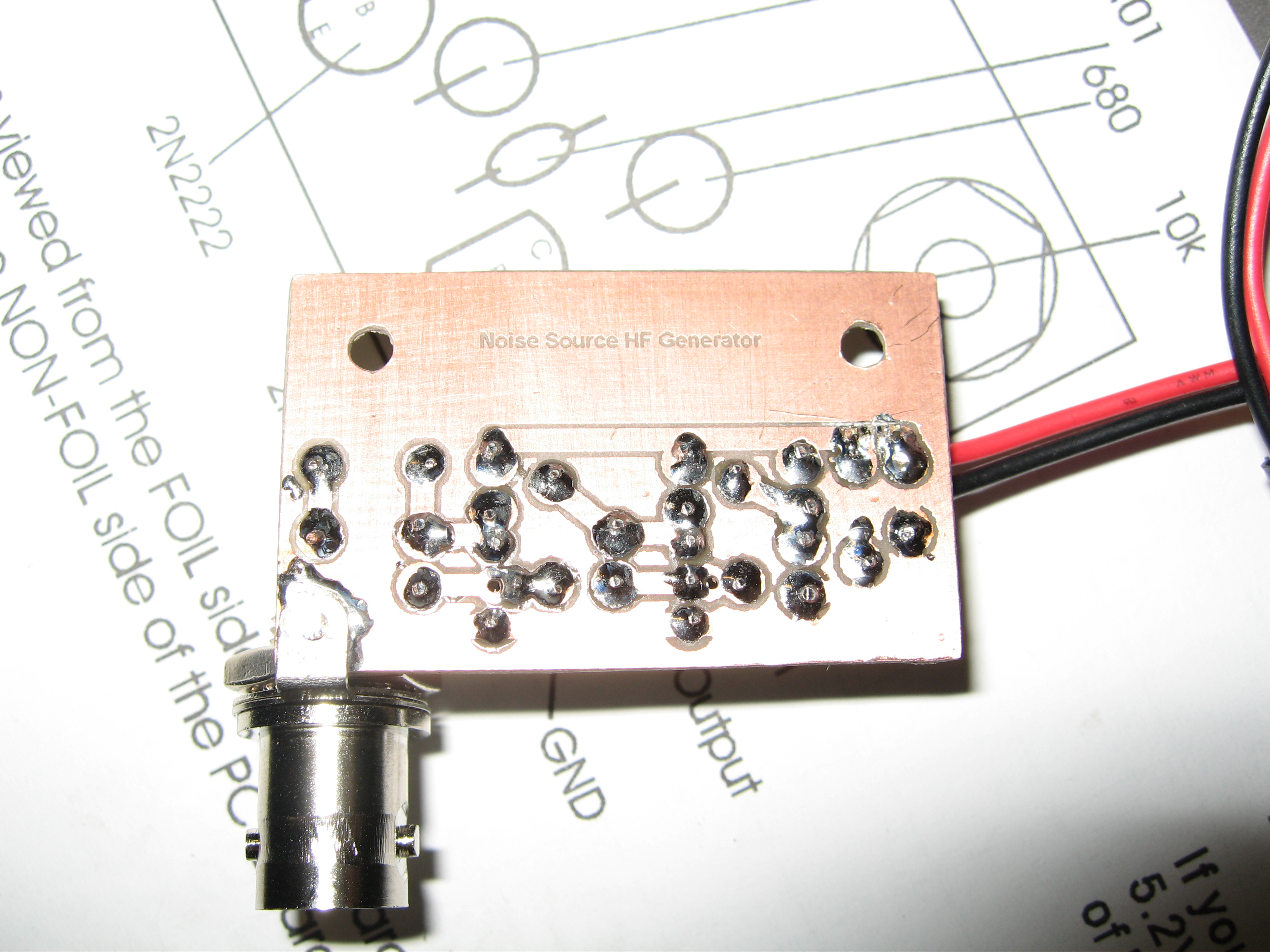
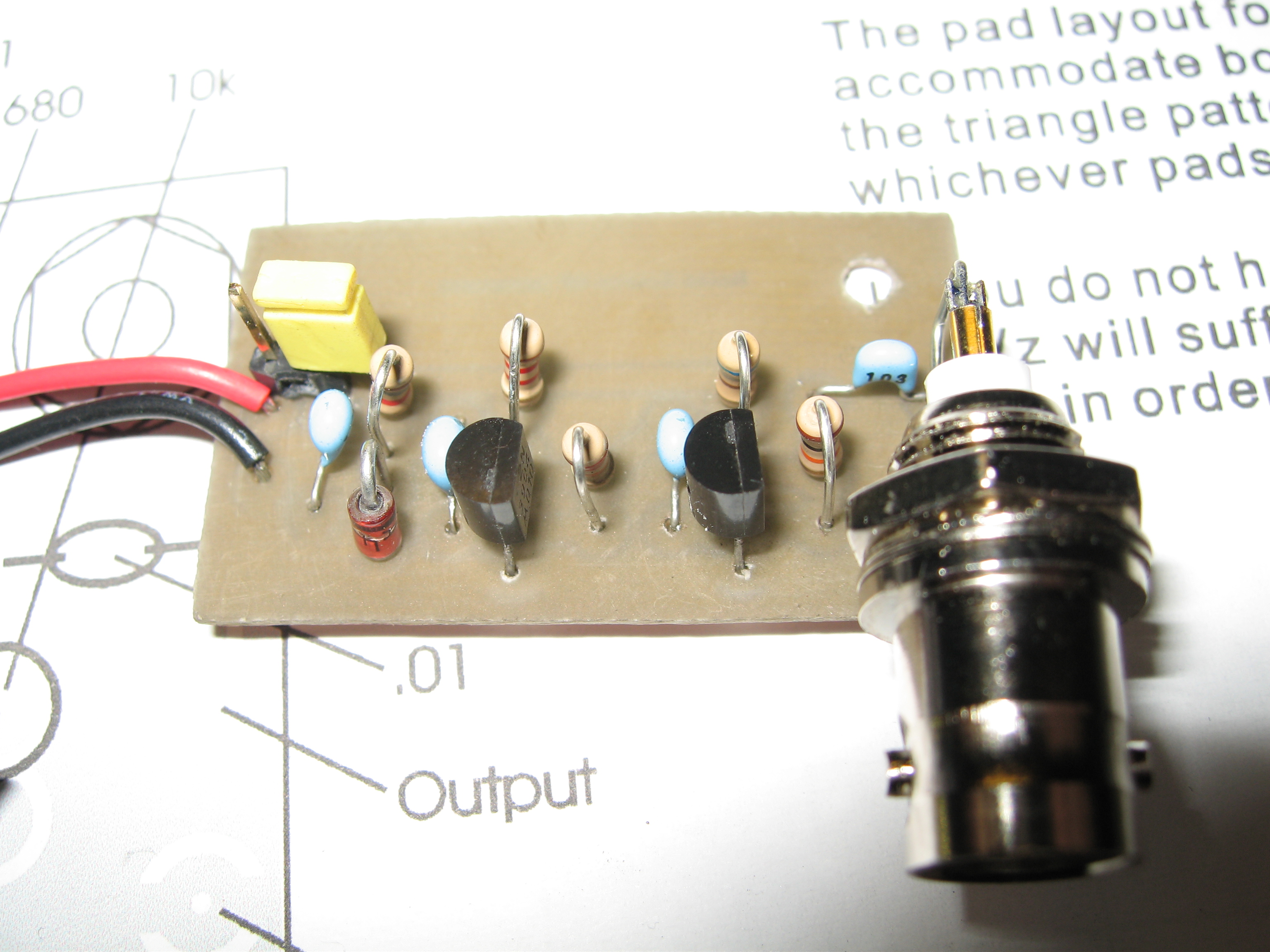
11-07-05
Noise source generator
This is my noise source generator for testing
receivers for ham radio and setting up the filter.
![]()
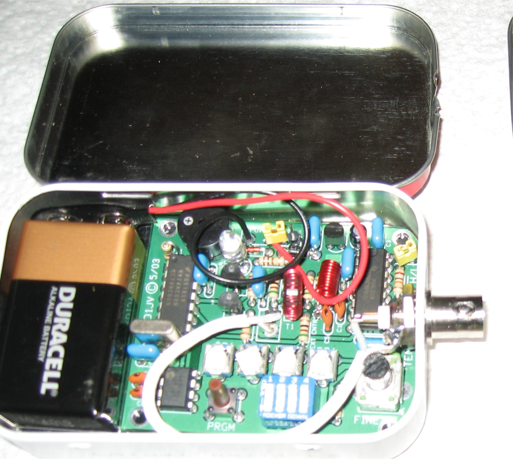
updated:
11-07-05
Tenna Dipper Kit
This is a nice kit for checking the resonant
frequency of an antenna.
![]()
updated:
11-07-05
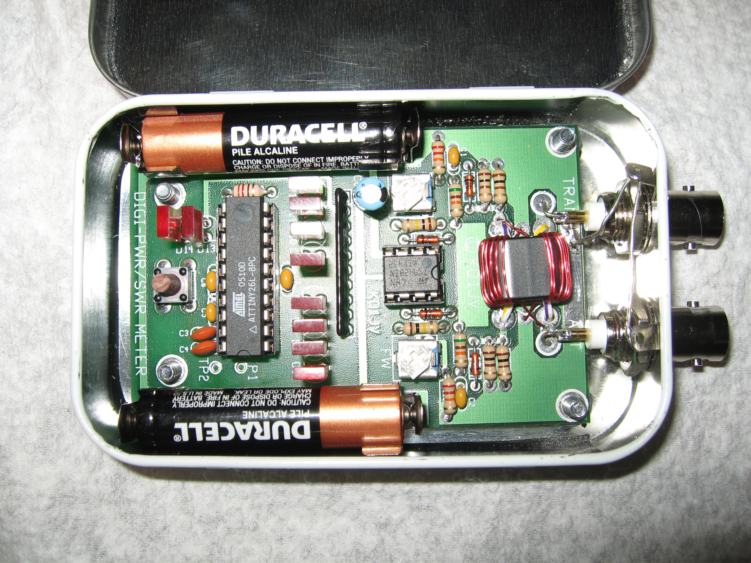
SWR/Power meter kit
This is my QRP power/swr kit that I put
together
![]()
updated:
11-07-05
Scantool ISO kit
This isn't finished yet, but I etched the board
and still need some parts to finish before I
order the chip.
![]()
updated:
9-30-05
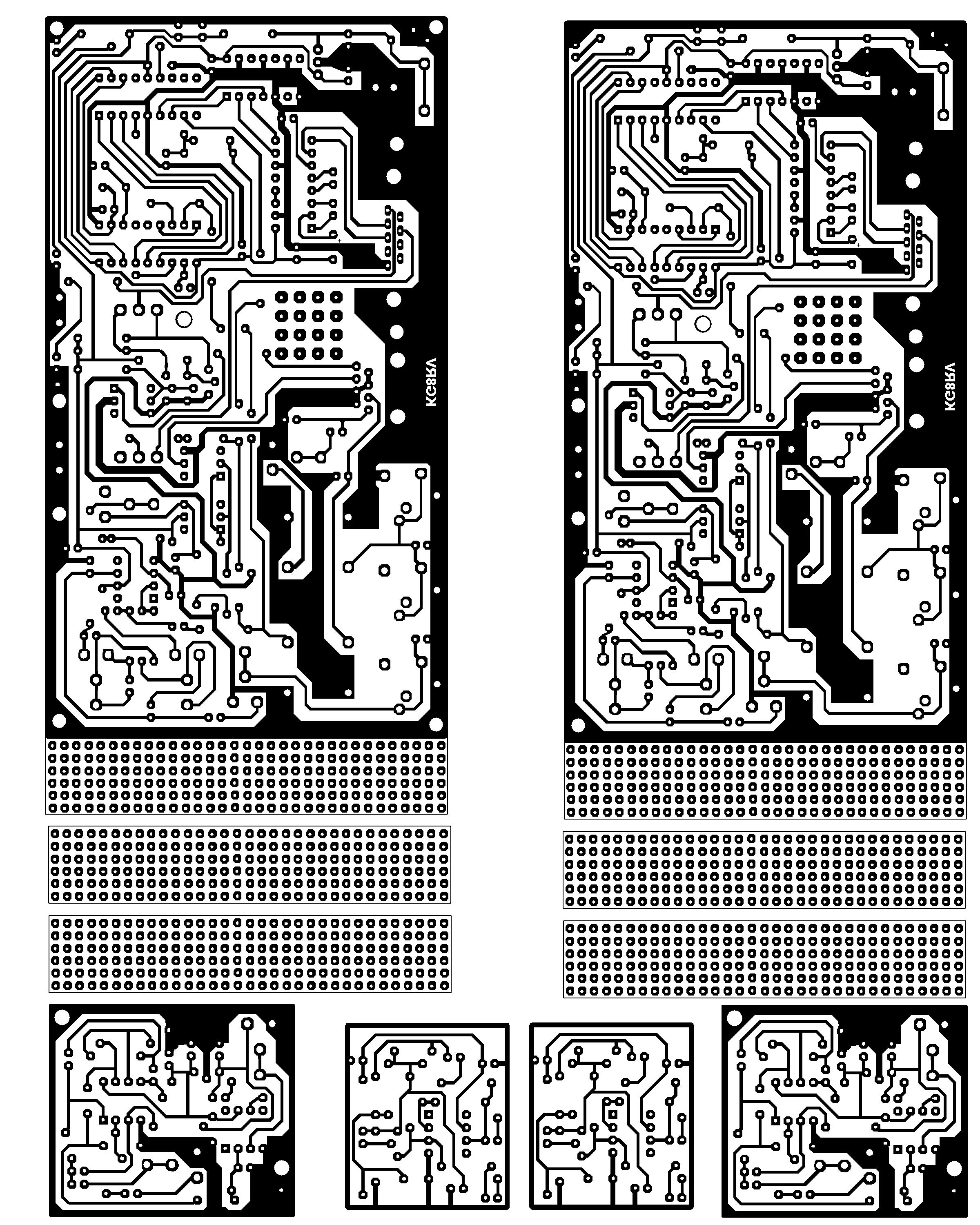
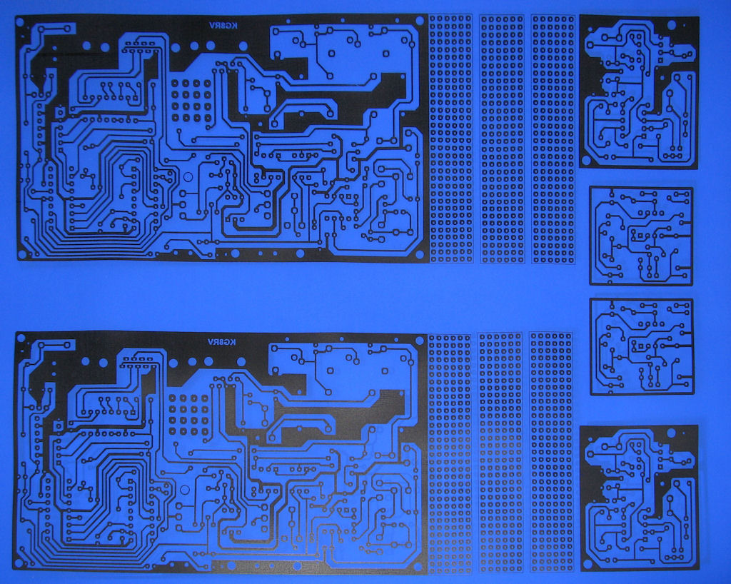
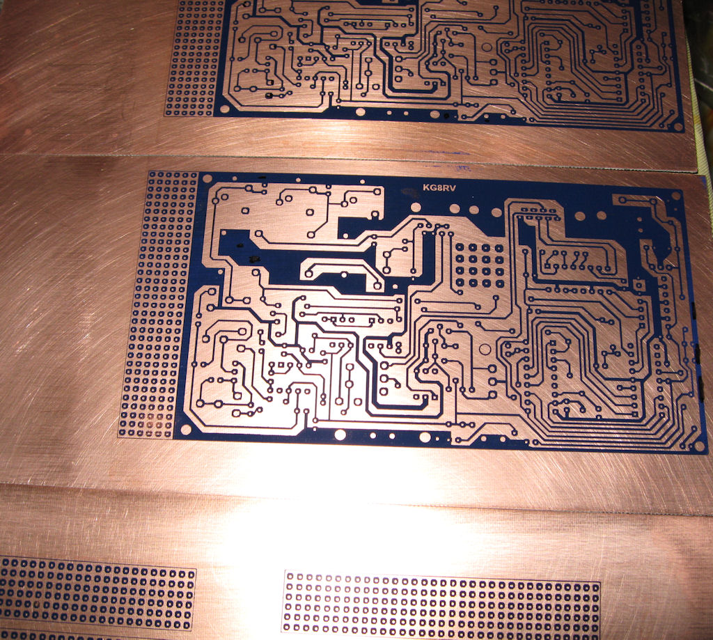
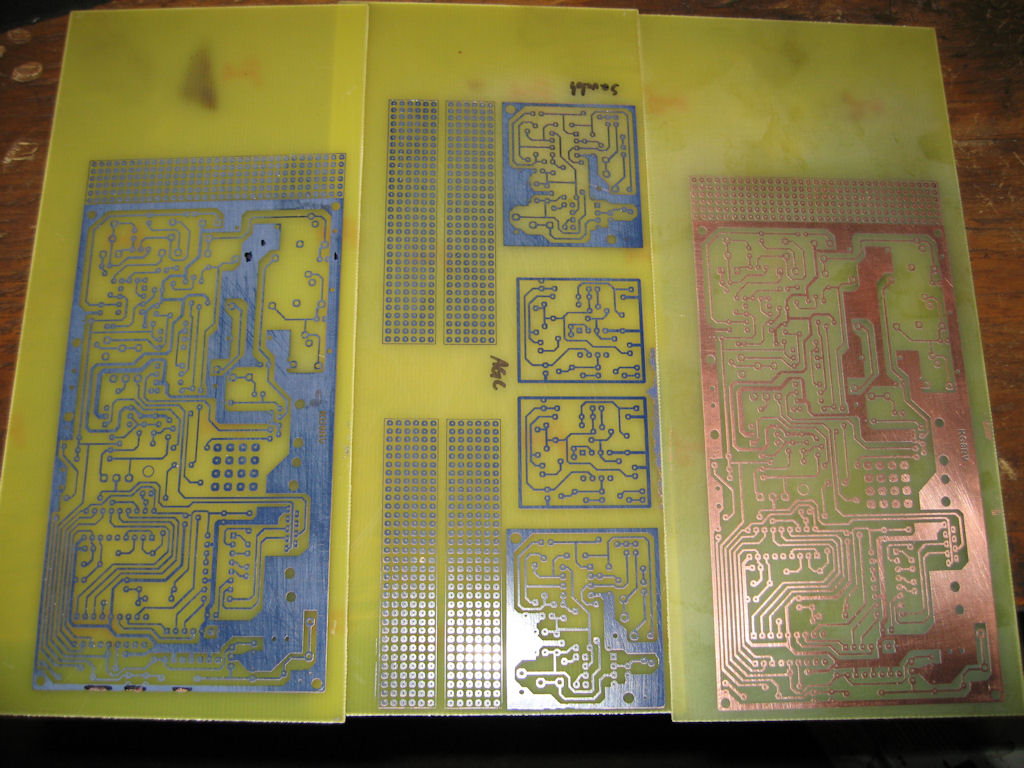
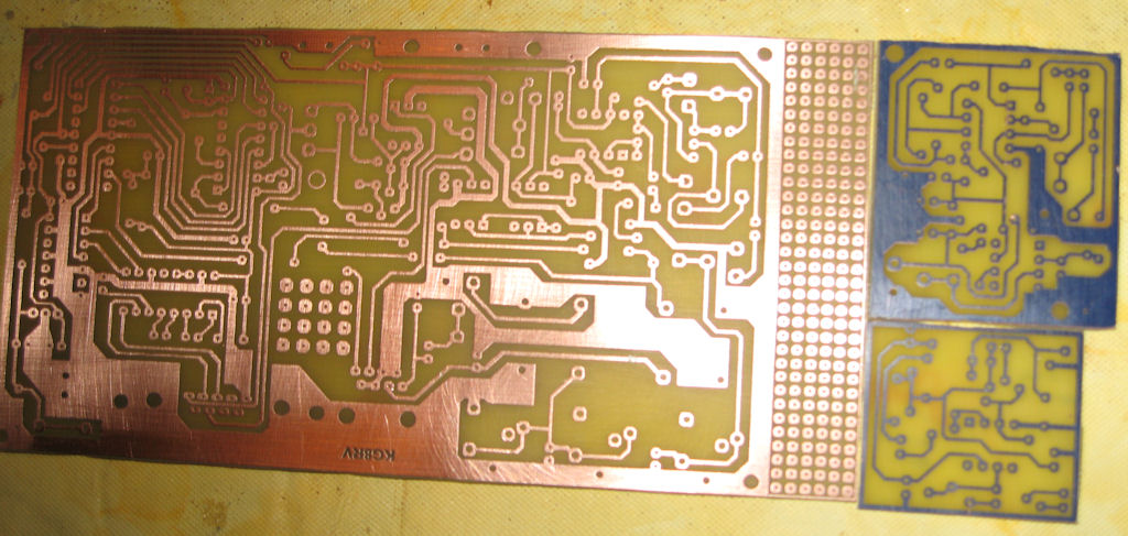
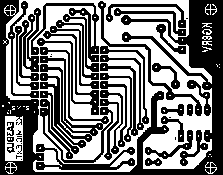
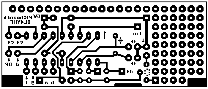
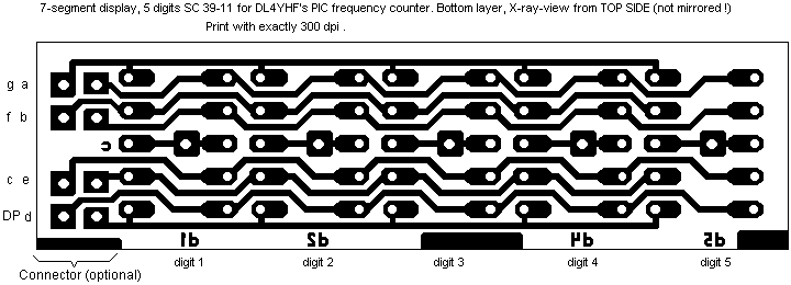
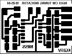
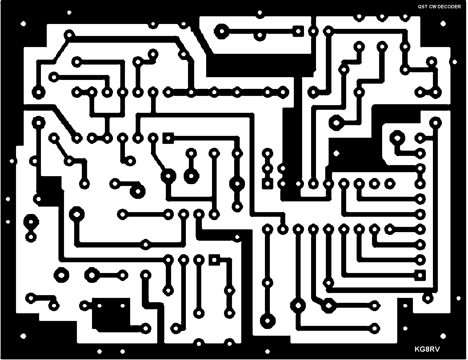
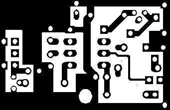
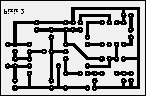
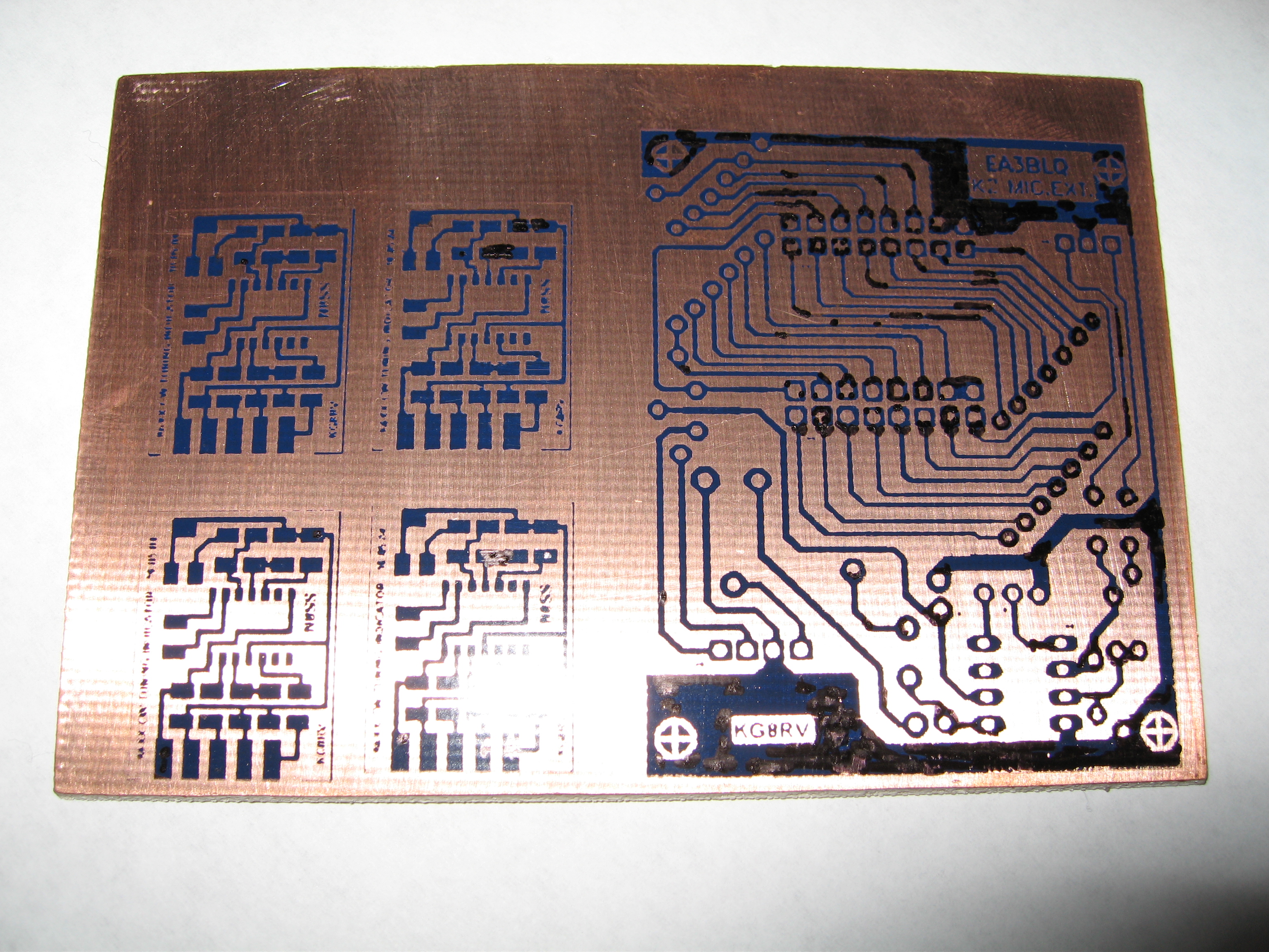
Elecraft K2 radio mods
This is where I started making my own pc boards
for mods for the radio. I wanted to add a data port
and a cw tuning indicator circuit and couldn't find
anyone who sold the boards so I made them myself
from the drawings I downloaded off the internet. I will
post the final pictures and board layouts when done. I
had to redraw the mic extension/data port board as the
one I found showed 2 layers and the one layer version
drawing had the jumpers drawn on so I removed them
in order to make my boards. I got all the stuff I needed
to make the boards and now I have more boards than
I know what to do with so if you need one, let me know
and we can work out the details on price then if interested.
These are the bmp's I used to etch my boards.
Please note that I put my call sign on these as
I had to convert them to bmp so I could print
them out and am in no way trying to take
credit for the work. I figured I did the work
to convert them and wanted my call sign in
my rig after completion so I modified them.
You are welcome to use what I have or get
them from the original authors but this is just
what I'm into and wanted to share incase
someone wanted them also.
Please note that not all of these are to 1:1
scale. If you see a 1x in the filename or
see a 300 as in 300dpi then it is 1:1 and
can be printed as seen otherwise you may
need to do some scaling. I plan on fixing
all the files here as I make them so keep
an eye out on the page.
K2 Mic extension w/data port (source)
frequency counter bottom (source)
Frequency counter top (source)
Pics:
![]()
updated:
8-03-05
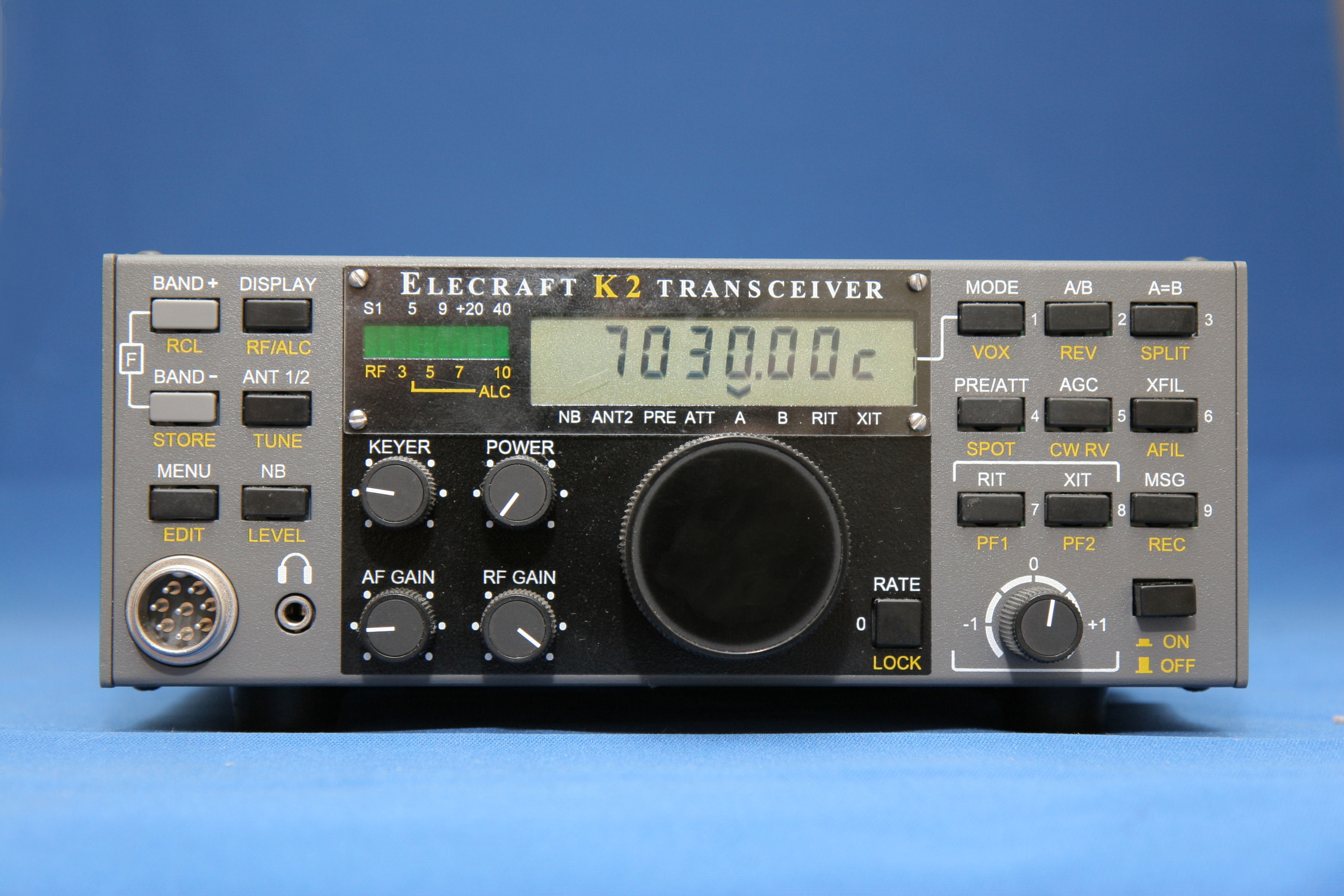
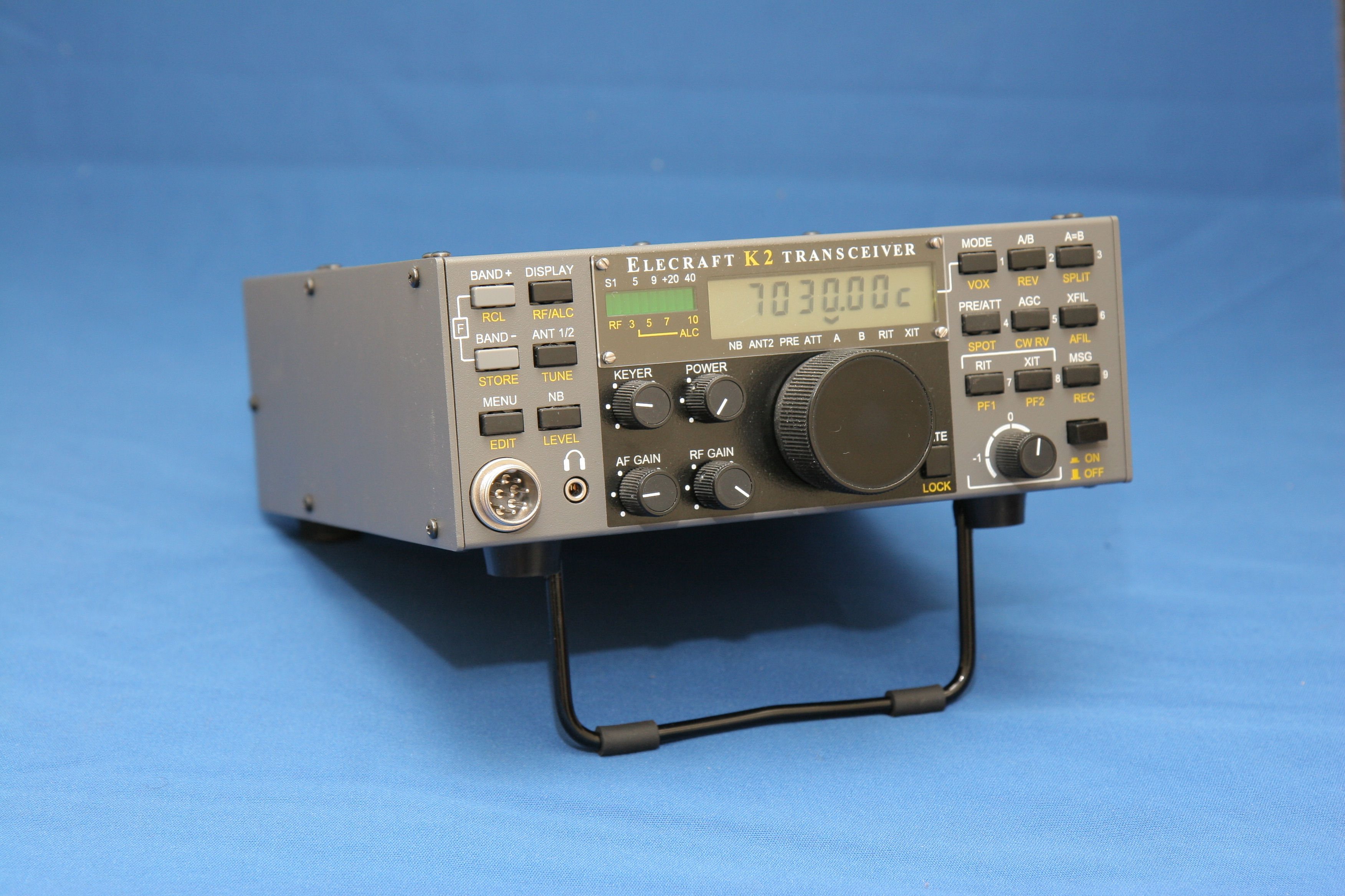
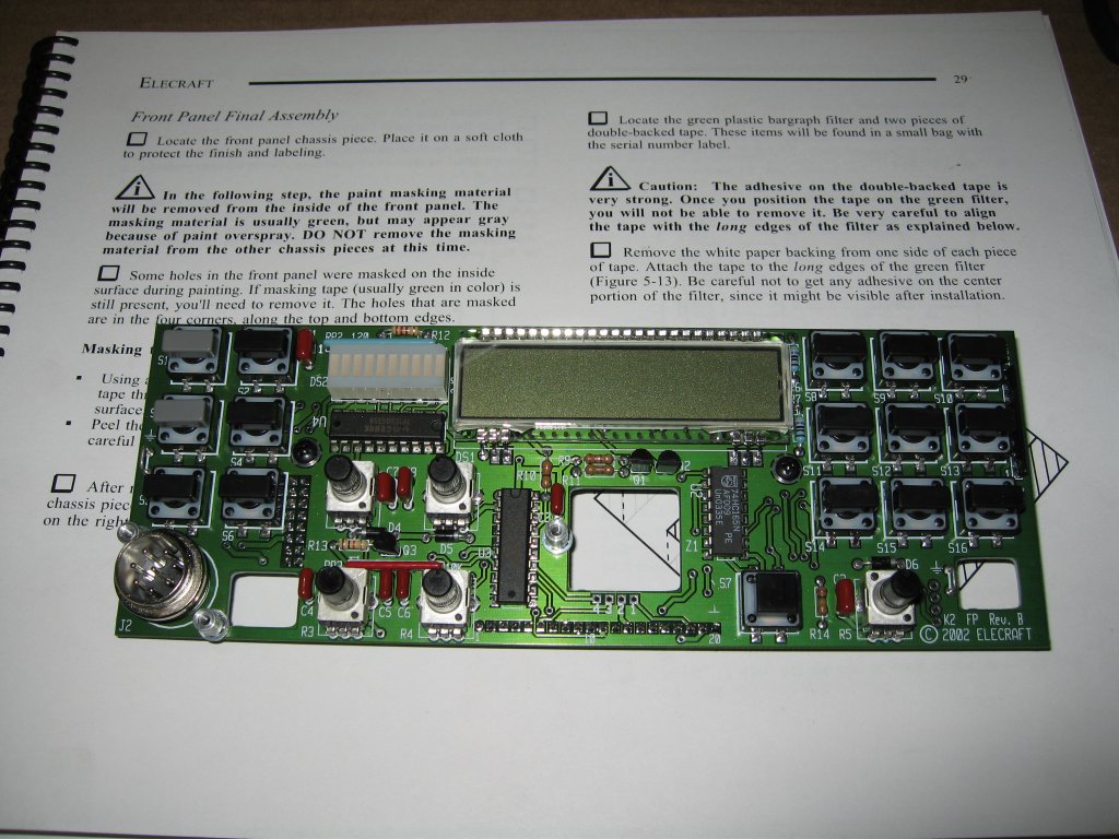
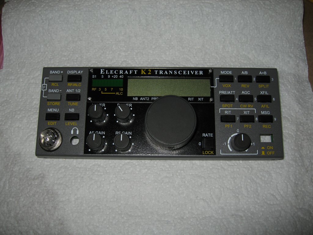
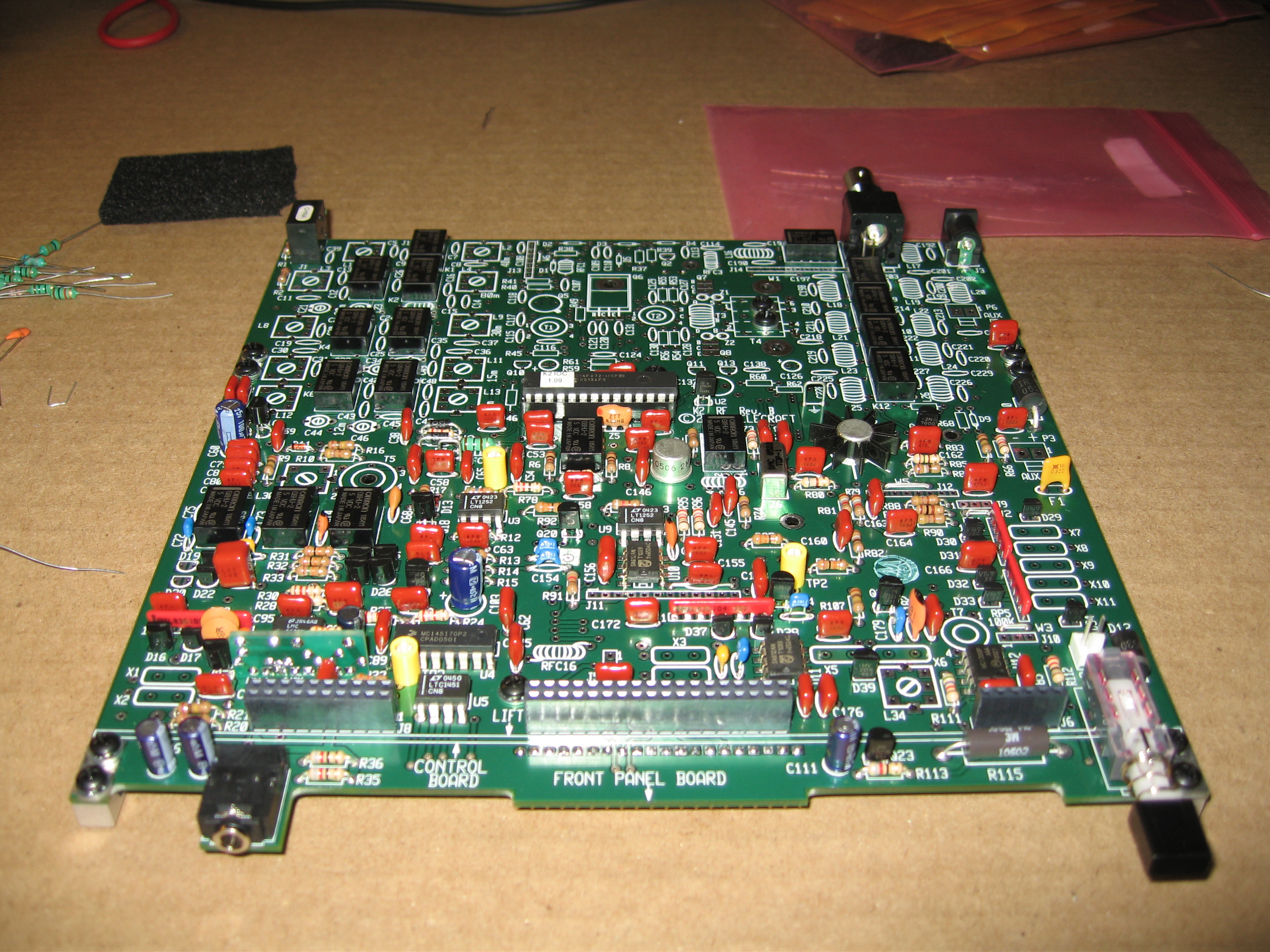
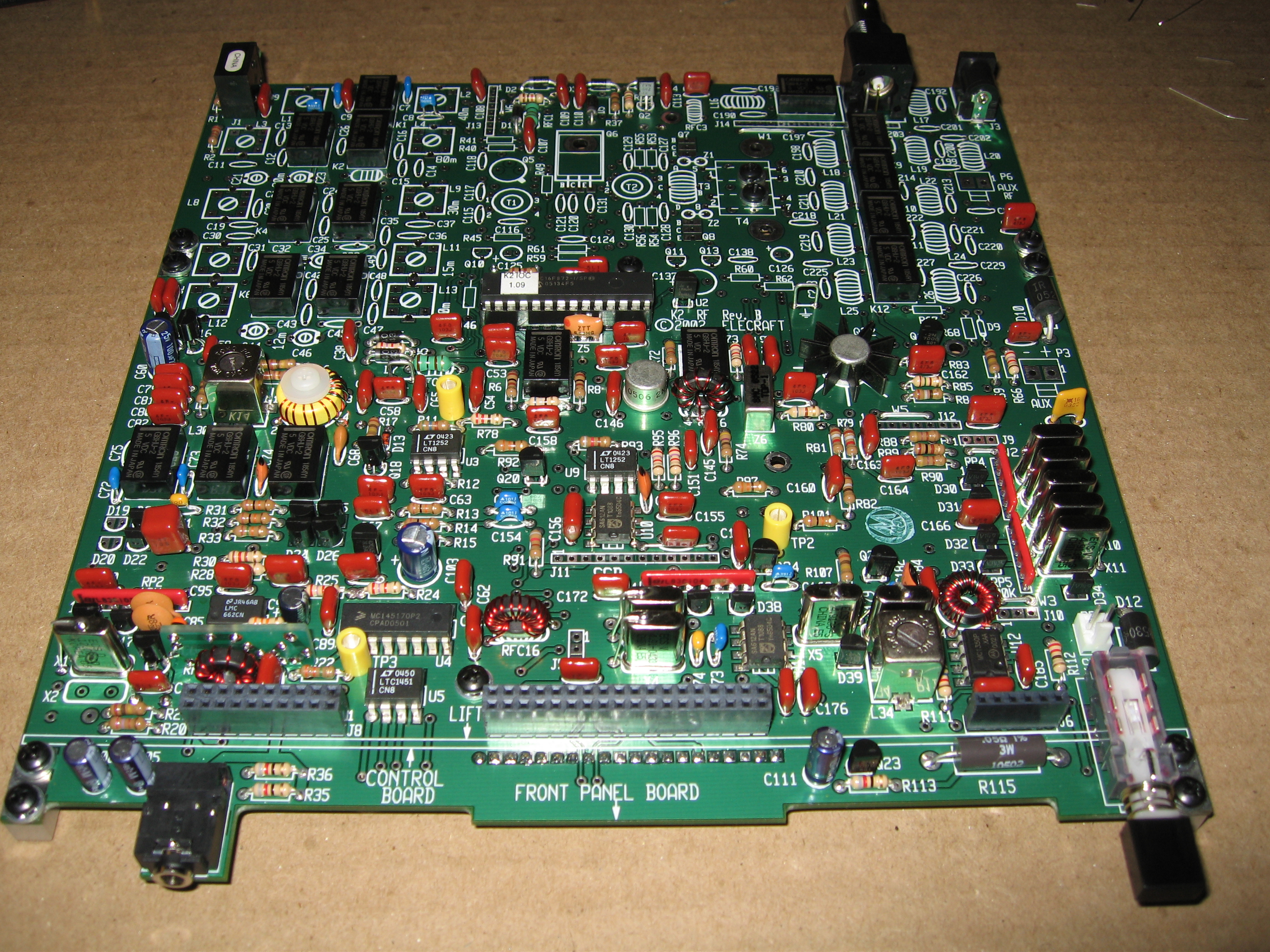
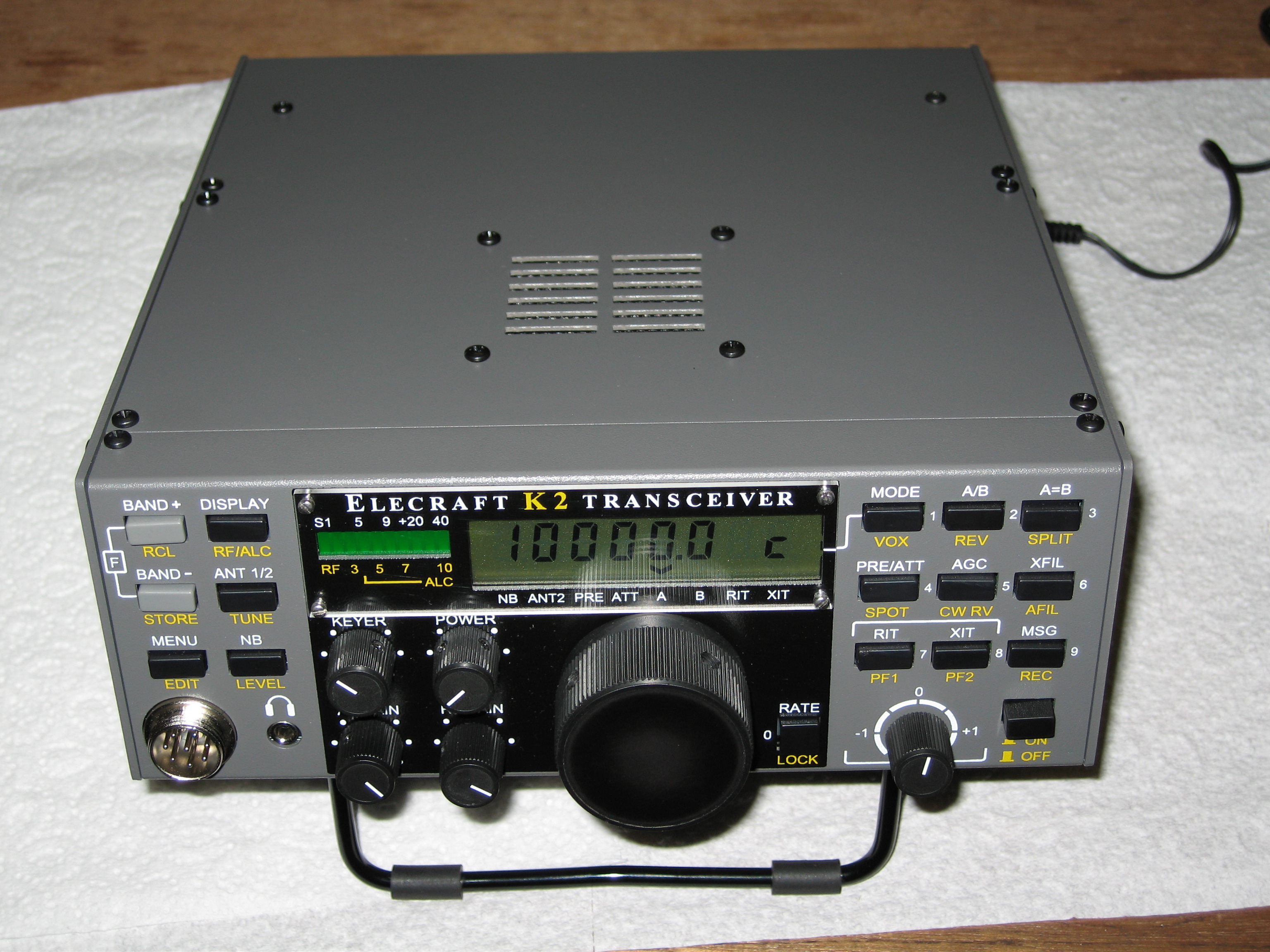
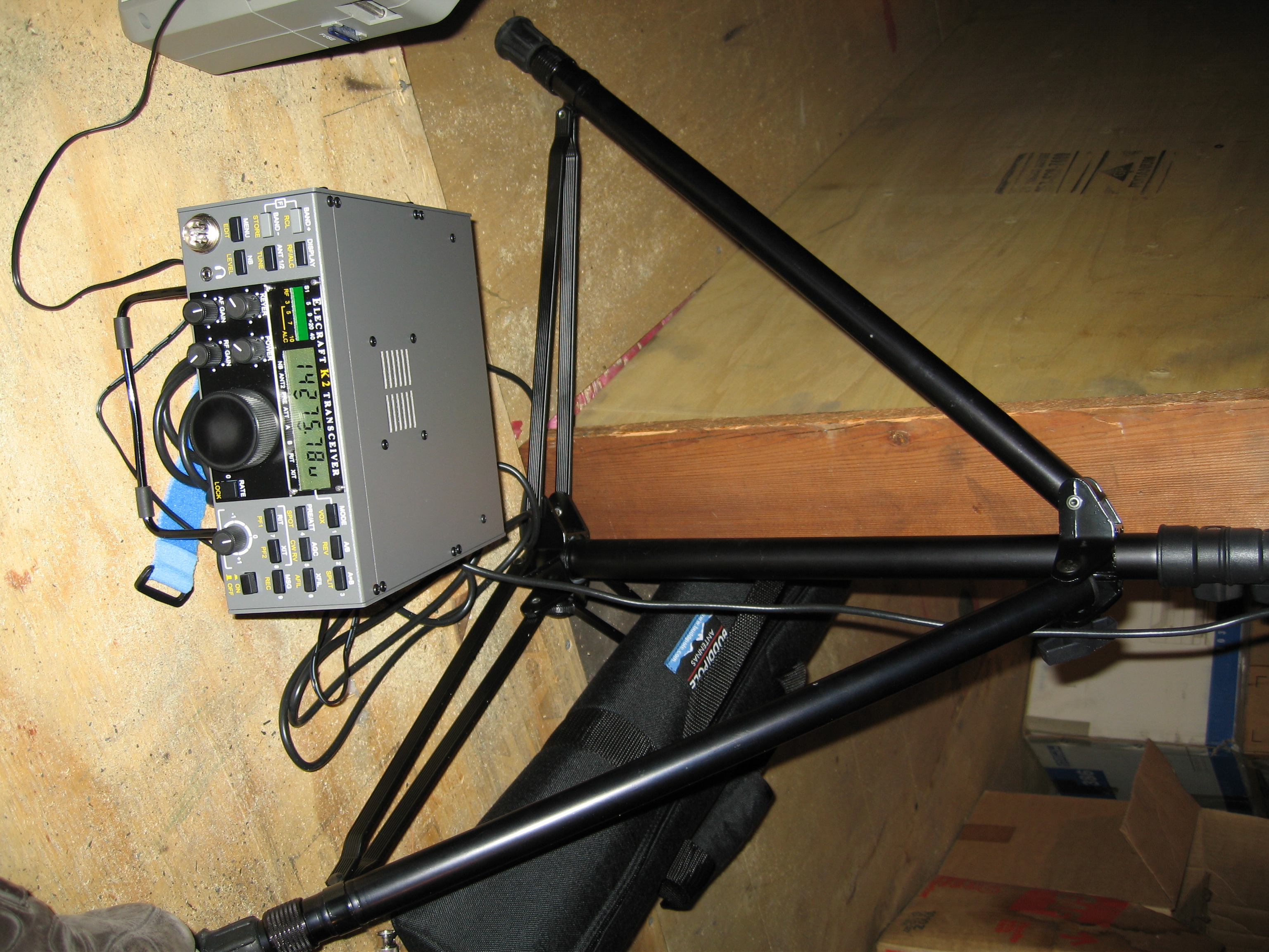
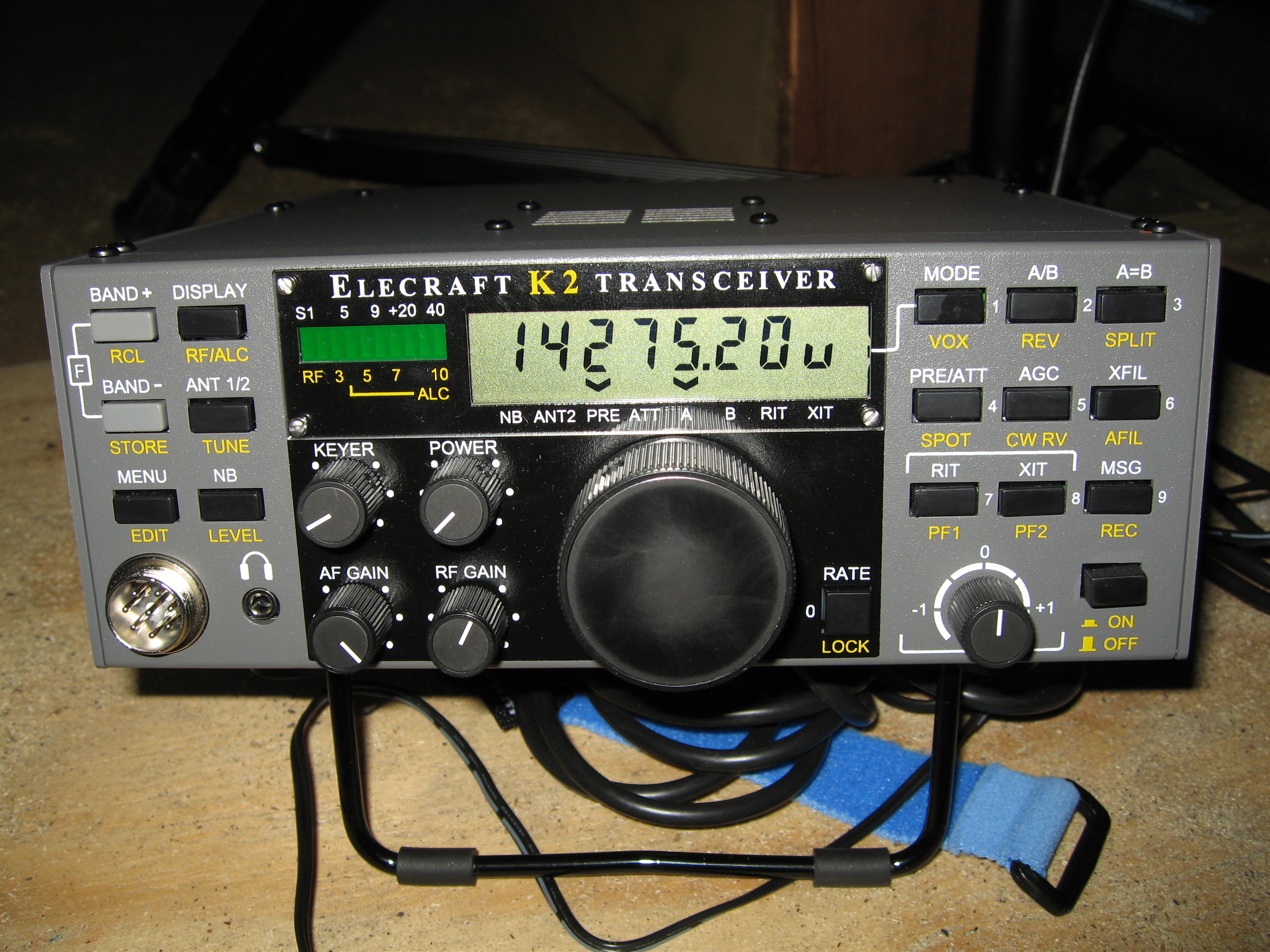
Elecraft K2 radio kit
This project will be an ongoing project as updates
to my progress will continue until the kit is built. I
bought the kit and got it in the mail 8-17-05 along
with my buddipole which is a really cool and
portable HF antenna that can be carried in a 24"
bag.
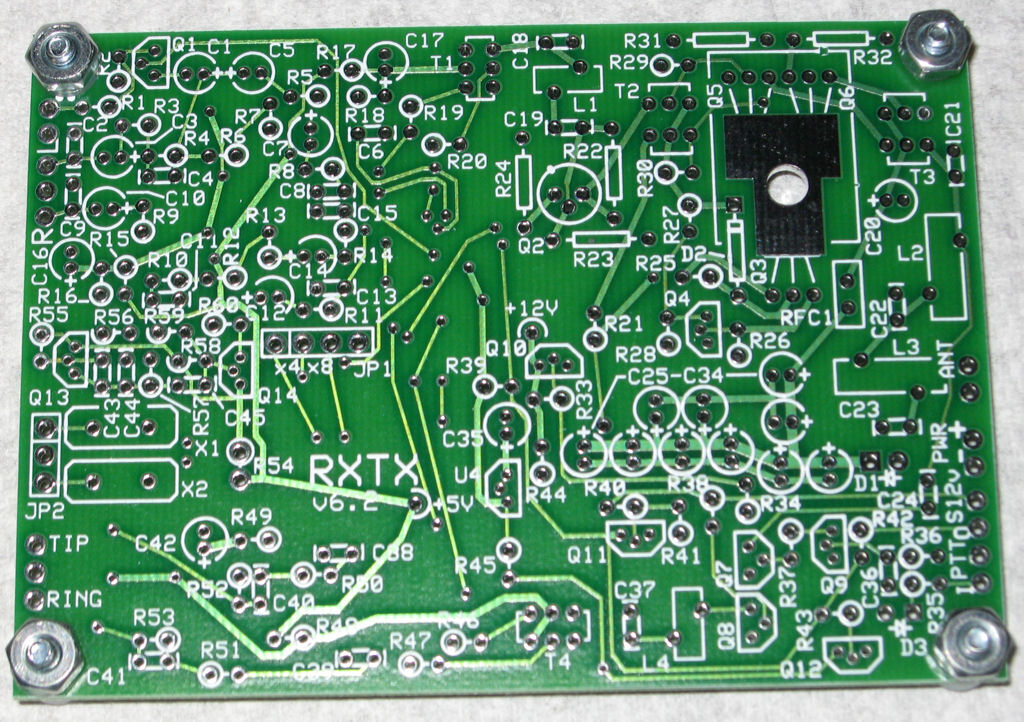
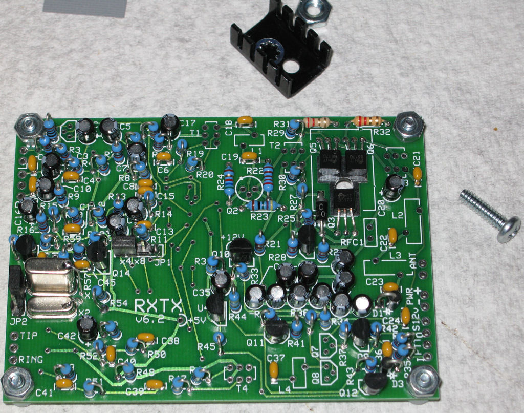
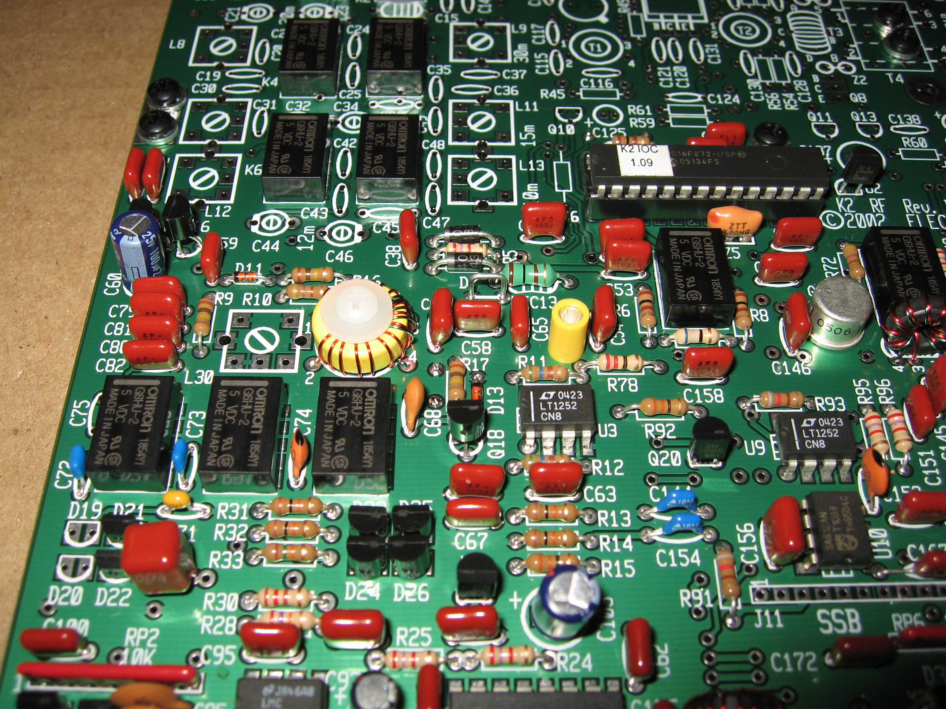
8-23-05
8-31-05
Hard lesson to learn...I found that all my windings
were wrong on the board. I counted the wires on the
outside of the core when you need to count the wires
on the inside for the correct count. I had to go through
and take 1 turn off of every coil including the T5
transformer which was putting out 8.2 volts and would
not change with L30 which I found out it is to increase
the voltage when going into the core. So corrected
everything and was able to get the 6 volts needed
on R30.
9-12-05
9-17-05
![]()
updated:
8-03-05
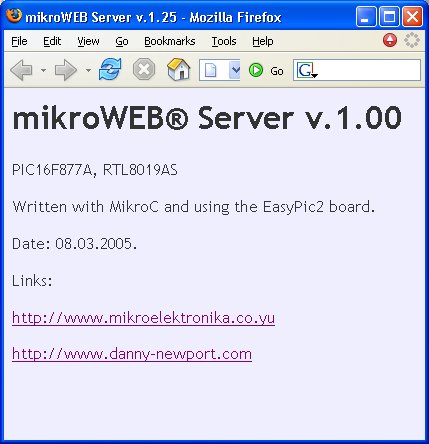
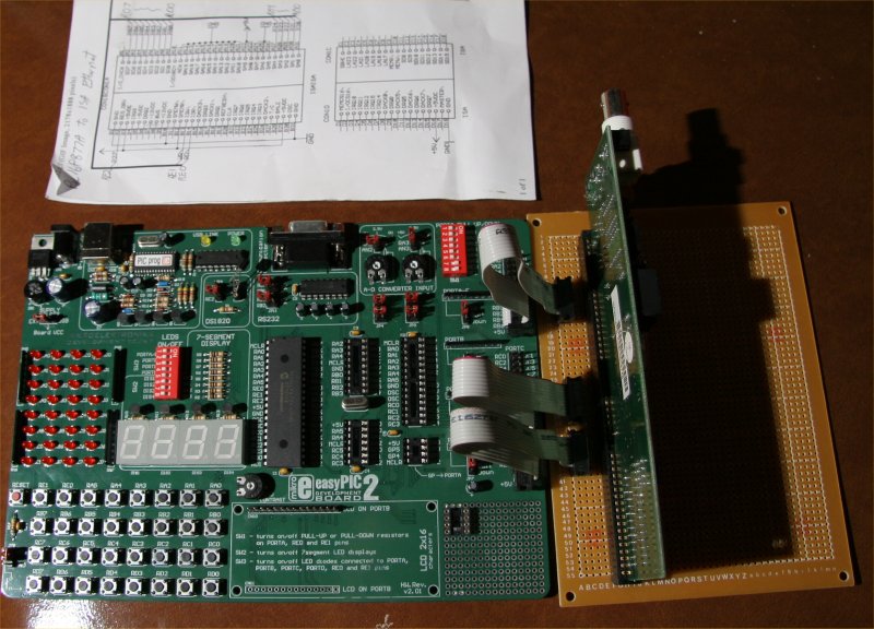
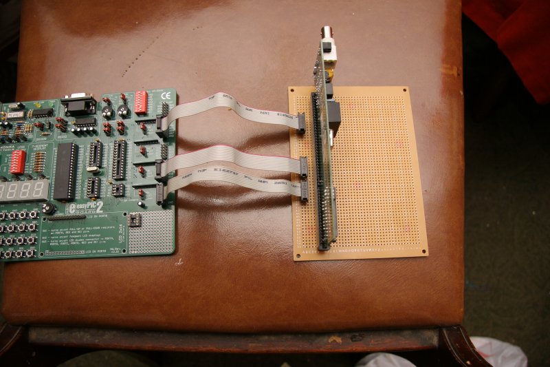
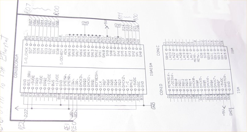
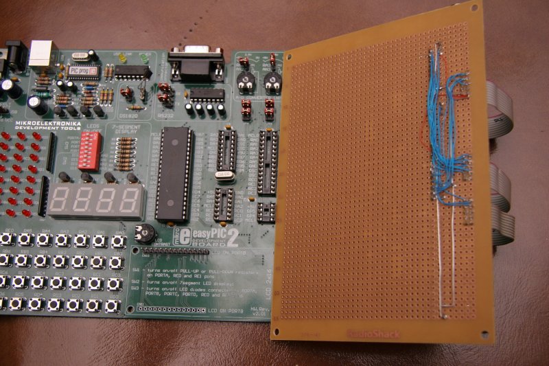
Pic 16F877A Embedded Ethernet
This project was written with MikroC to make a Pic
16F877a work with an ISA card for embedded Ethernet.
I modified the original source to meet my needs for the
ip address of my network and found a circuit here that
I modified to work with the EasyPic2 board and a few
minutes of soldering I now have a really cheap embedded
Ethernet to play with. I robbed the ISA card from one of
my old computer motherboards although I should have
used one from the board that went through the lightning
strike, but I got one basically for free, already had the
isa network card with the right chip onboard and paid
$5 for the circuit board from Radio Shack. The chip
was one that came with the EasyPic2 board so the
cost for me was very cheap after the purchase of the
EasyPic2 board. Of course you need the paid version
of MicroC to compile the hex file, but now the fun
begins. I have a few snapshots of my project also.
Overview with schematic I used
The source code is just a slightly modified
version that came with my MikroC demo.
Although registered version is needed to
compile the sample code.
![]()
updated:
7-12-05
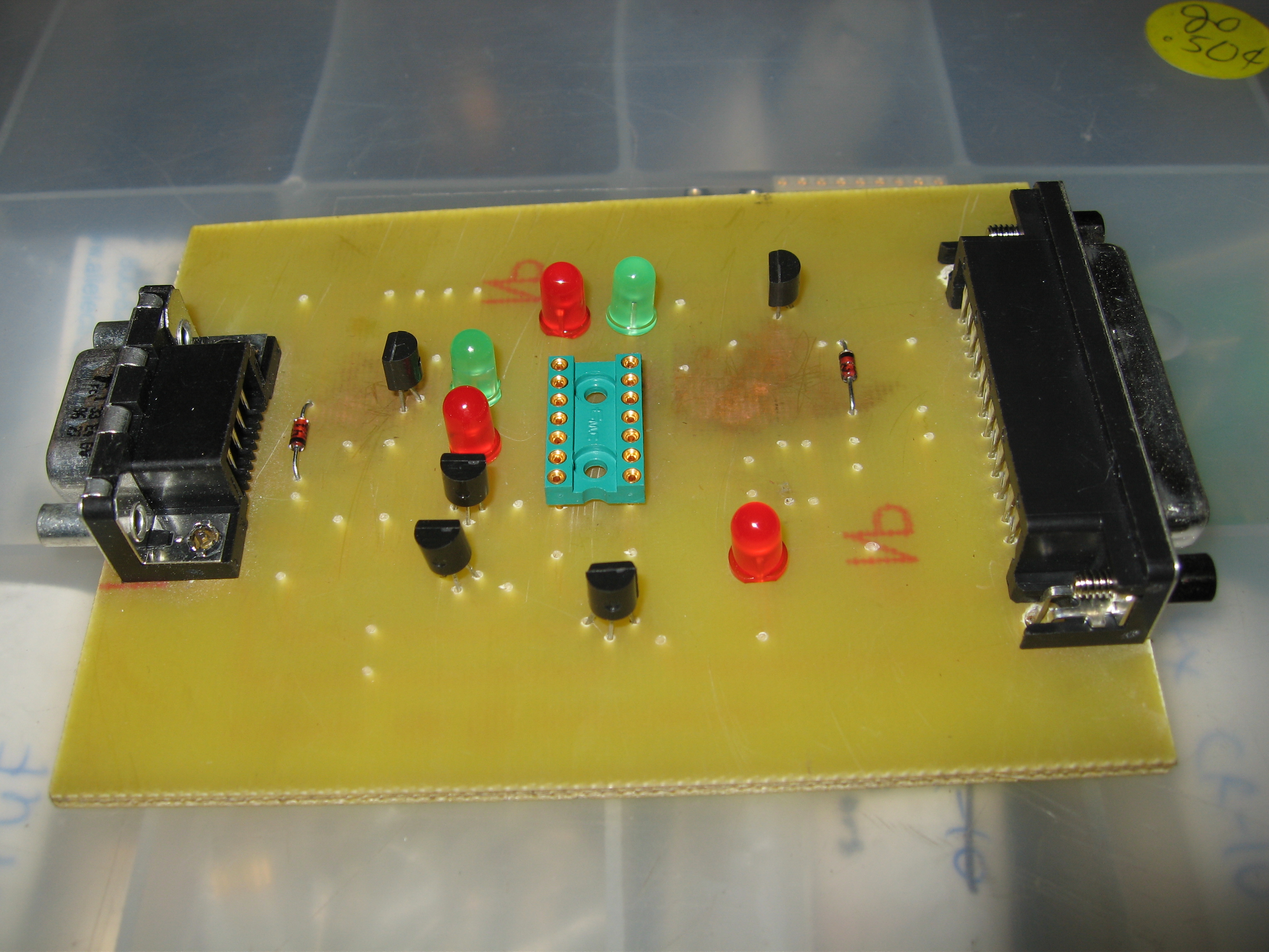
Pic 16F84a quiz unit
This project was written with MikroC to make a Pic 16f84a
act as a quiz unit. Pins 0-3 on PORT A are for outputs and
Pins 0-3 on PORT B are for the inputs. Whichever input is
pressed (tied high) first wins with a corresponding output.
The source code below includes the hex file needed to
program the chip and use the reset light to reset the quiz
unit.
![]()
updated:
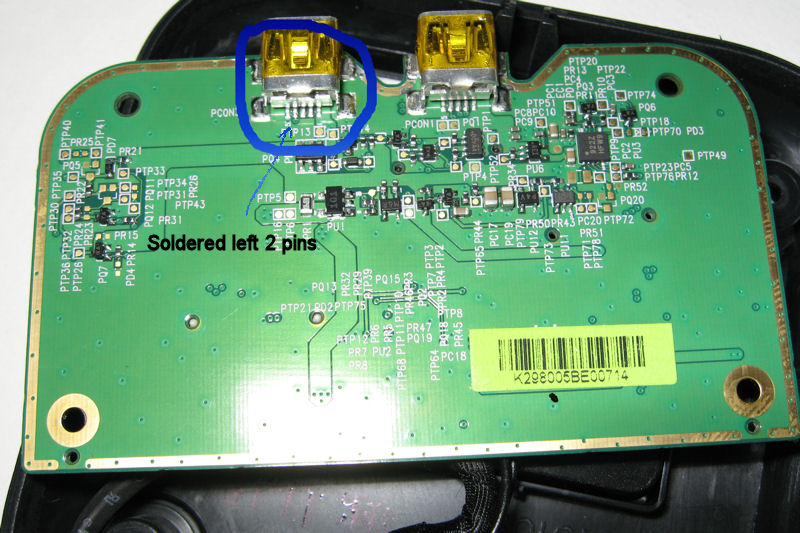
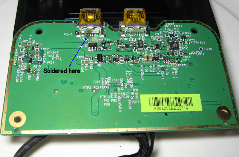
5-9-05
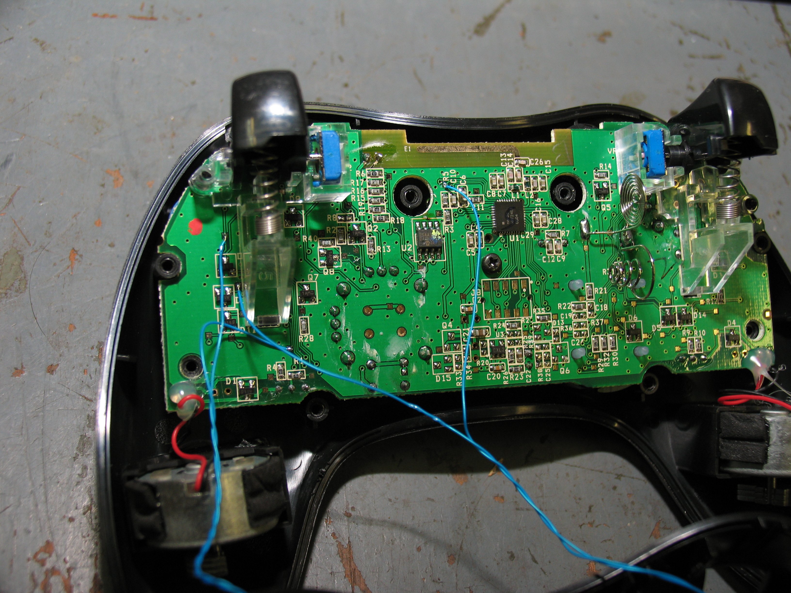
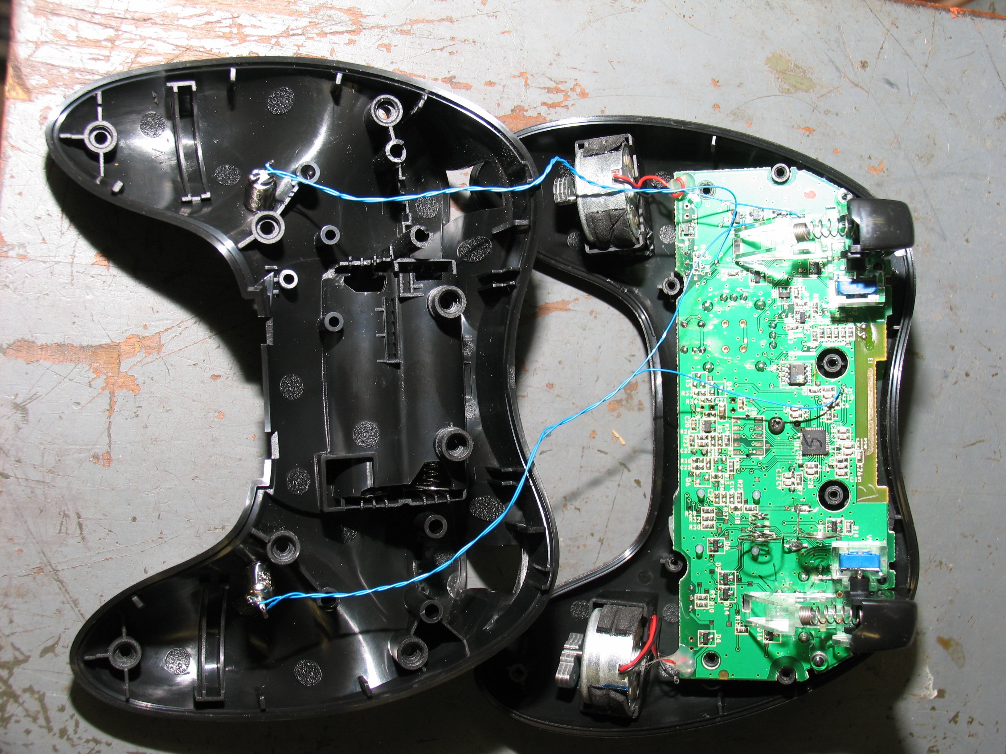
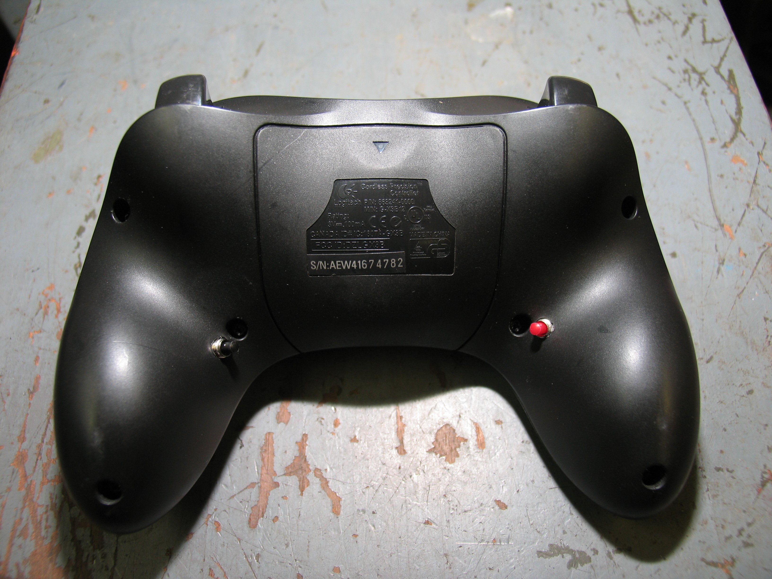
Logitech Xbox Controller Hack
This project was done to assist in my game playing.
I didn't like the fact that I had to let go of the controls
in order to jump or do a punch (A and B buttons) while
playing the game. I like keeping my hands and thumbs
in one spot all the time when possible. So I found the
traces on the circuit board to solder switches to and
paralleled mini switches to them under the controller
where my other fingers could get to without releasing
control of movement and aiming. This isn't meant for
a tutorial on how to hack your controller, just shows
what I've done to mine to increase playing ease.
The pics are high enough res that you could use
them to make your own mods if you want to but
don't blame me if you damage your controller.
I will warn that on the one side of the controller I
was a bit off and had to carve away some plastic
in order to get the switch to clear the vibrator
motor frame so I could put it back together.
Either way, here is my hack and I'm pretty
happy with the outcome and look forward to
playing more with the mods. Check out some
pics of the mod while you are here.
![]()
updated:
5-11-05
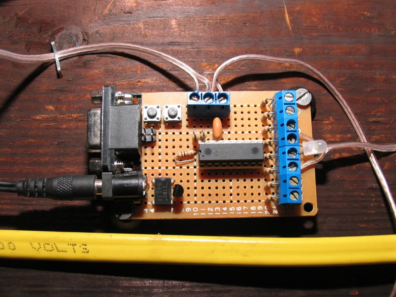
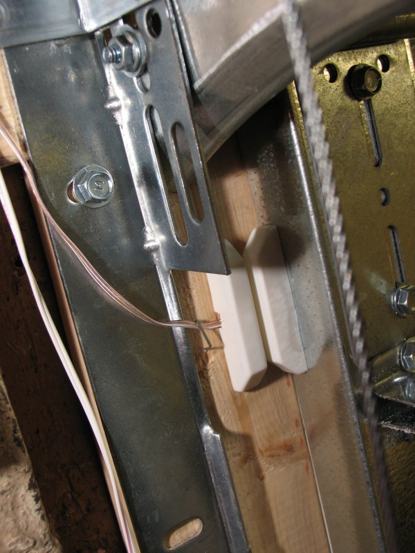
Garage door indicator
This project uses a pic micro to control a set
of led's to show if my garage door is up or
down and even in between. I use PORTA
for input using pins 0 & 1 for the door switches
and I use PORTB for the output of all the led's.
I haven't actually built the circuit yet so this is
only the preliminary part but it is here if you
want to give it a try. I got the idea for this
circuit from ELM ELECTRONICS.and the
program was written using MikroC
which is a really cool compiler. I liked all the
features it had to offer right off the bat with all
the classes setup to do lots of things the easy
way.
update:
5-11-05
Well, I actually got the circuit installed and all
wired up and working. The picture shows the
switch I used that I got from Radio Shack and
the circuit board has 2 PB's on them to simulate
the door switches which was used for testing.
I also have an rs232 port which I decided not to
use and it is only partially hooked up and no
software was written for it either.
update:
6-10-05
I got the LED's installed in my Mom's smoke
alarm for the circuit and is working pretty well.
![]()
updated:
2-22-05
status:
done.
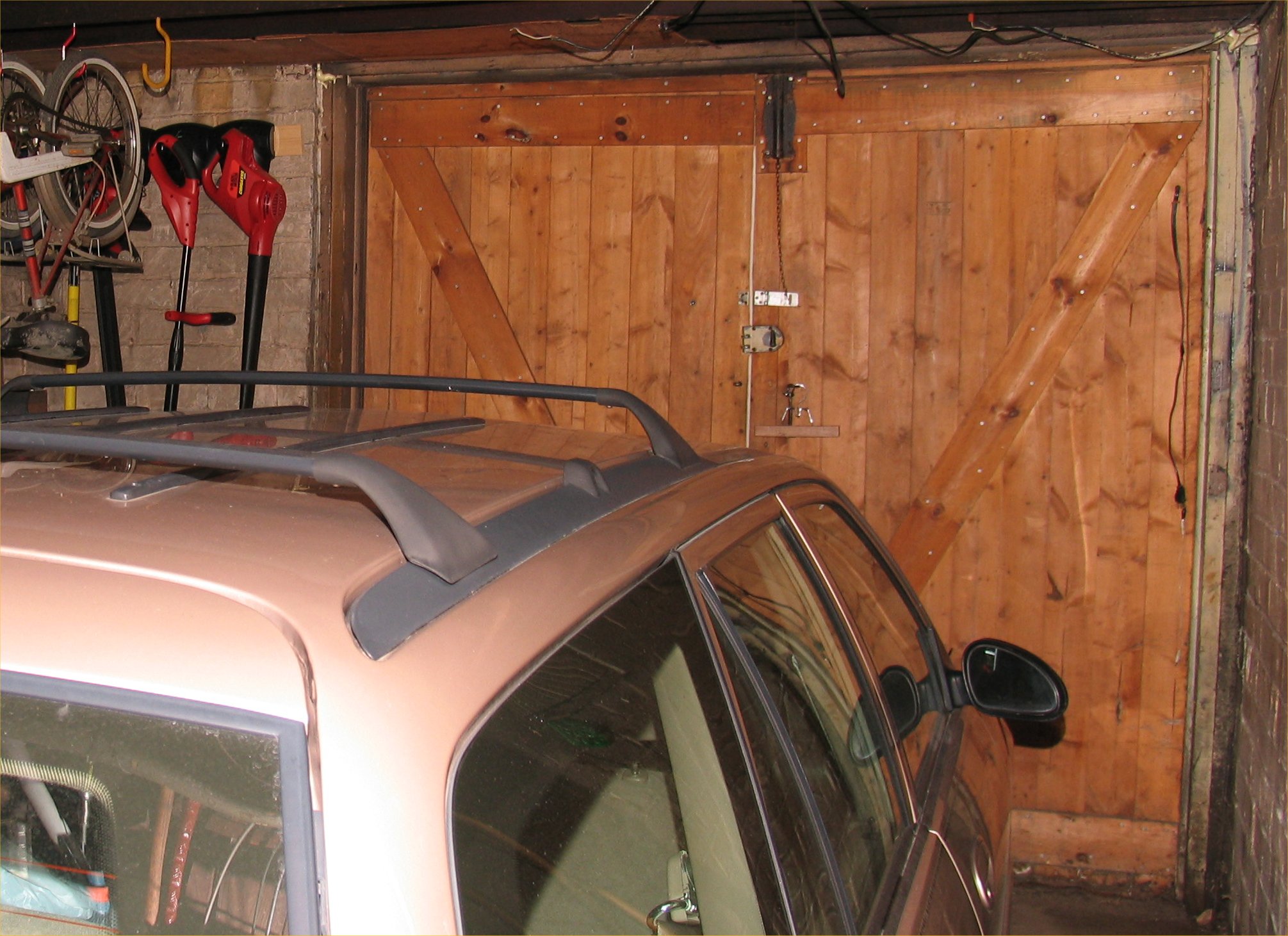
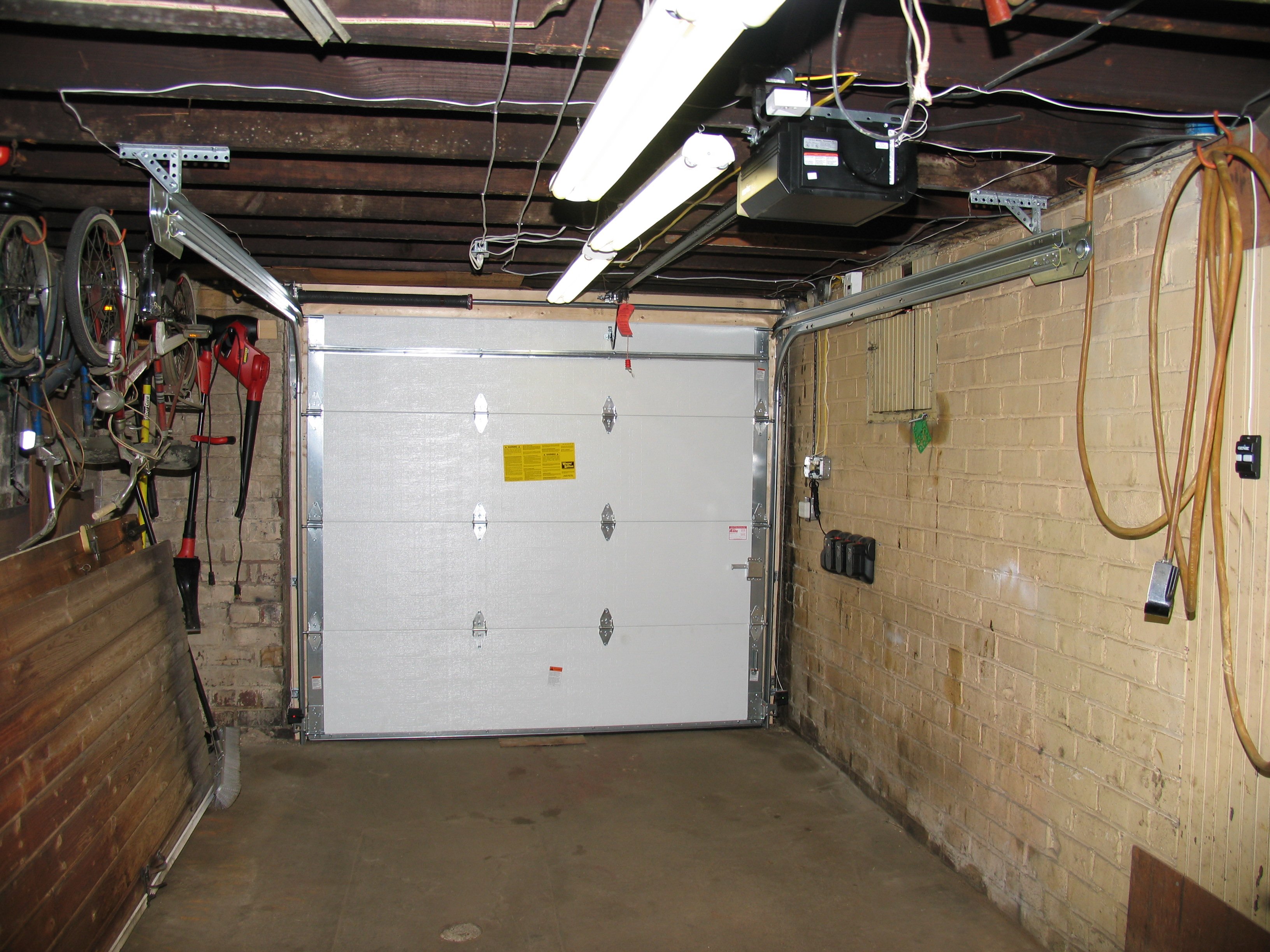
Garage door project
This project was actually more of an expense than a
project although I had to rewire the garage to make
way for the door.
![]()
updated:
11-12-04
Get a Free Ipod project
This is my link for a free ipod? I just signed up for
it and will see if I ever get a free ipod or not. I'll update
once I actually get one if it works.
![]()
updated:
5-11-05
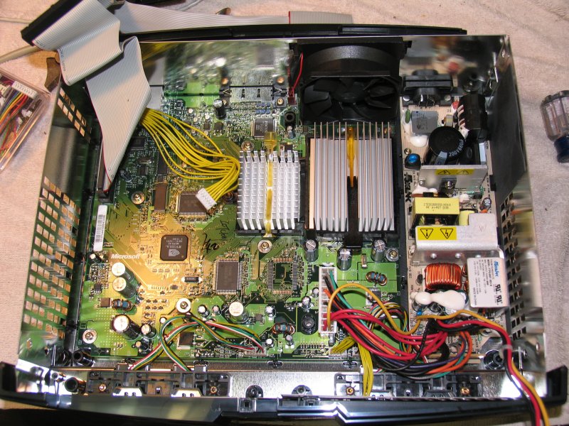
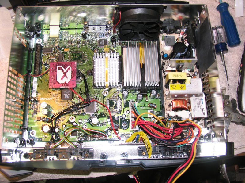
Xbox, hack the Xbox
This is my xbox before and after the installation of
the X3 modchip. Mods are pretty easy to do but
the Linux installs don't seem to like my video too
well, so more pictures of it in use later.
update:
10-28-04
I have successfully installed Gentoox on my xbox
and have surfed the internet with it and even used
samba to access the drives and stuff. I have a
keyboard and mouse installed which I bought the
Logitech's wireless mouse and keyboard which
only needs one usb port for them. Pictures
and other info to follow.
update:
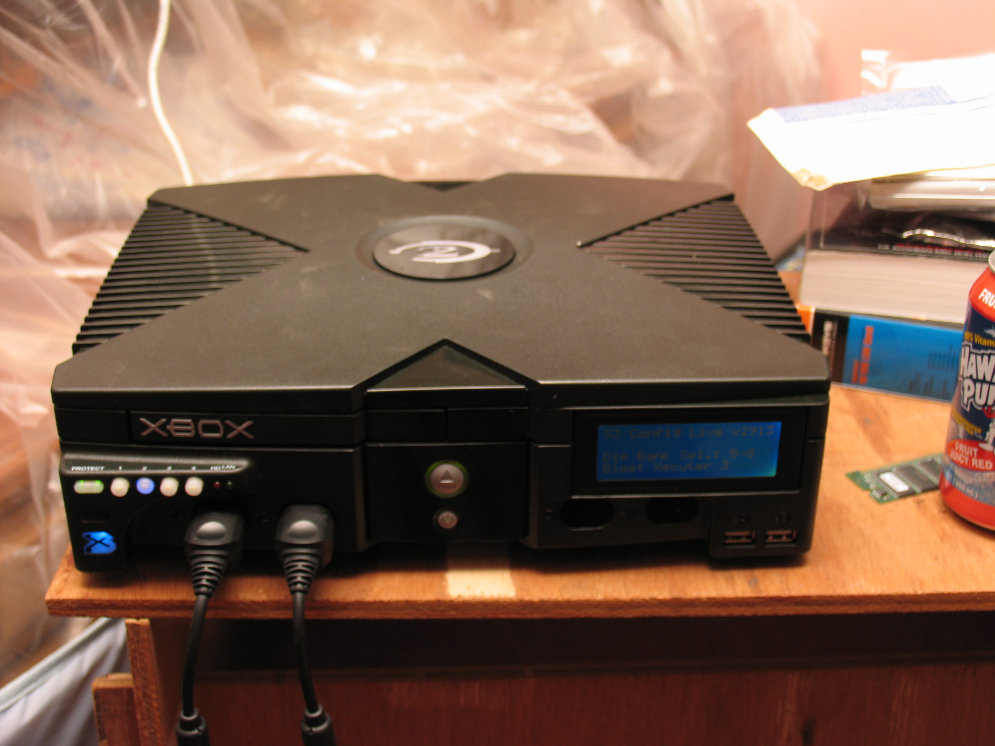
2-22-05
Installed a front panel with lcd to let me know the
xbox load, ip address and whatever else I can think
of to display on the lcd as long as there is support for
it anyway. I also added a top light with a Halo 2
symbol which looks pretty cool.
update:
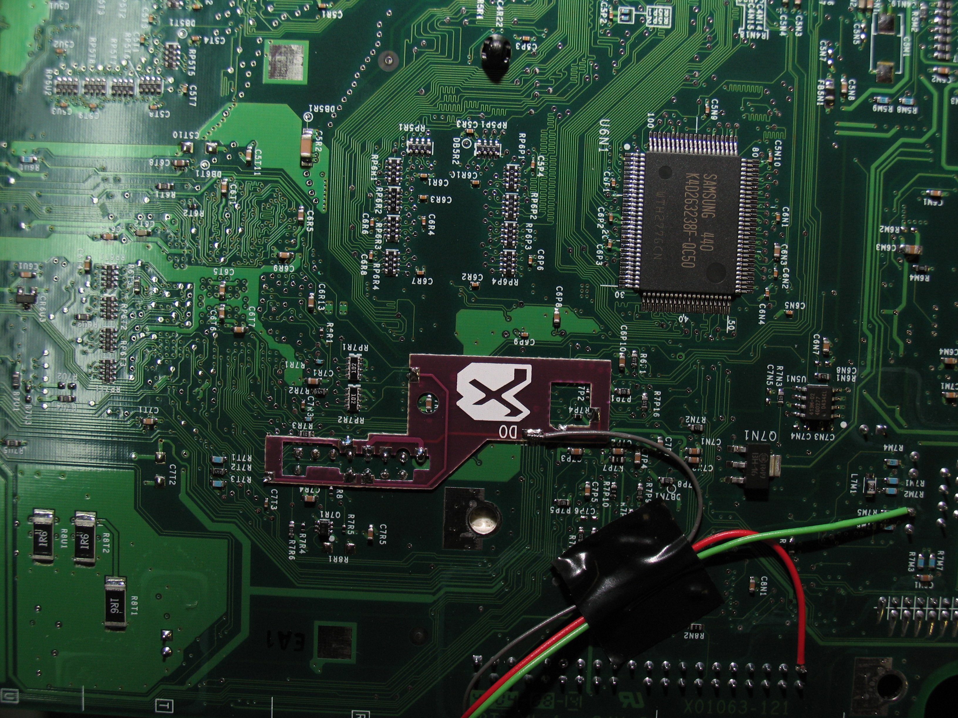
3-2-05
Installed the LPC rebuild on an xbox 1.6 version
and here are some pictures.
update:
5-11-05
Ok, now I modified my xbox some more. I changed
the green led for the HD light back to the blue one
for the X3 chip and I changed the standard green
light to blue ones for the eject button light. I also
started playing around with X-DSL which is pretty
cool and it runs on less than 50megs.
![]()
updated:
10-17-04
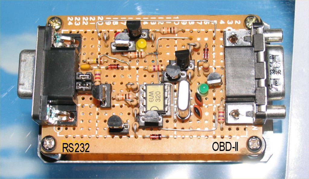
Elm320 PWM car Scanner
This is a circuit I built for my Brother-in-law for
him to check his Mustang with. He gets lots of
use out of it and I get enjoyment of building it.
Circuit can be found at scantools.net if you care
to build one yourself or you can order a pre built
one like I did for myself.
![]()
updated:
8-15-04
Multifunction Logic Probe
This is my second version of the "super probe" that
I made. The circuit isn't my design but it is a very
useful tool to have around the shack. I built the
first one just like the one in the link and liked it
very well. I made this one as I purchased 2 sets
of chips and displays and all the cutout work was
finished by hand and to my surprise it all turned out
really well. The circuit design and chip code can
be downloaded via the super probe link above.
![]()
updated:
8-9-04
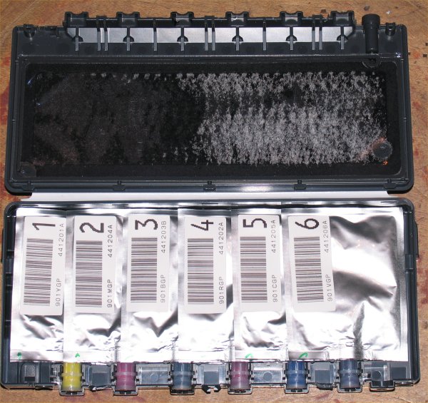
Insides of a Picturemate Ink Cartridge
Here is the insides of the Epson Picturemate 4x6 printer
ink cartridge. There is a chip located on the bottom
that serves no purpose other than to lock the printer from
printing after 100 pictures have been printed even though
there is lots of ink left. My black is about half full and the
other ones are at least 1/4 full. I need to find a hack to fix
the chip problem so I can just keep printing until I run out
of ink and start getting bad pictures then install the new
cartridge and save even more money on printing my
own pictures.
![]()
updated:
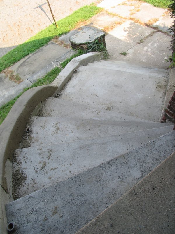
8-9-04
Front steps rework.
This project is just a very needed one. I
had to tear out my old cement steps and
pour new ones.....I don't think I'll ever do
that again.
![]()
updated:
8-12-04
Motion IR Commander
This project using the learning remote chip,
motion sensing chip and an AVR 2313 as
the brains to control everything. I have it
working pretty well. I hook a camera up to
the back of the box, then hook the VCR
up to the other jack and add power. Now
when the circuit senses motion, the cpu
tells the IR remote chip to transmit the
signal to record. After 25 seconds or
so it tells the vcr to stop unless there
was onther sense on motion and in that
case it gives it another 25 seconds before
telling the vcr to stop. To test the circuit
I used channel up and down to see if it
worked and so far it works pretty good.
This way I can have motion sensing security
on my vcr without using up 6hrs of record
time unless something is moving and I don't
have to hack my vcr and I can reprogram
the box to turn my stereo on and off or
control anything that uses IR to make it
work.
Motion VCR control box circuit
![]()
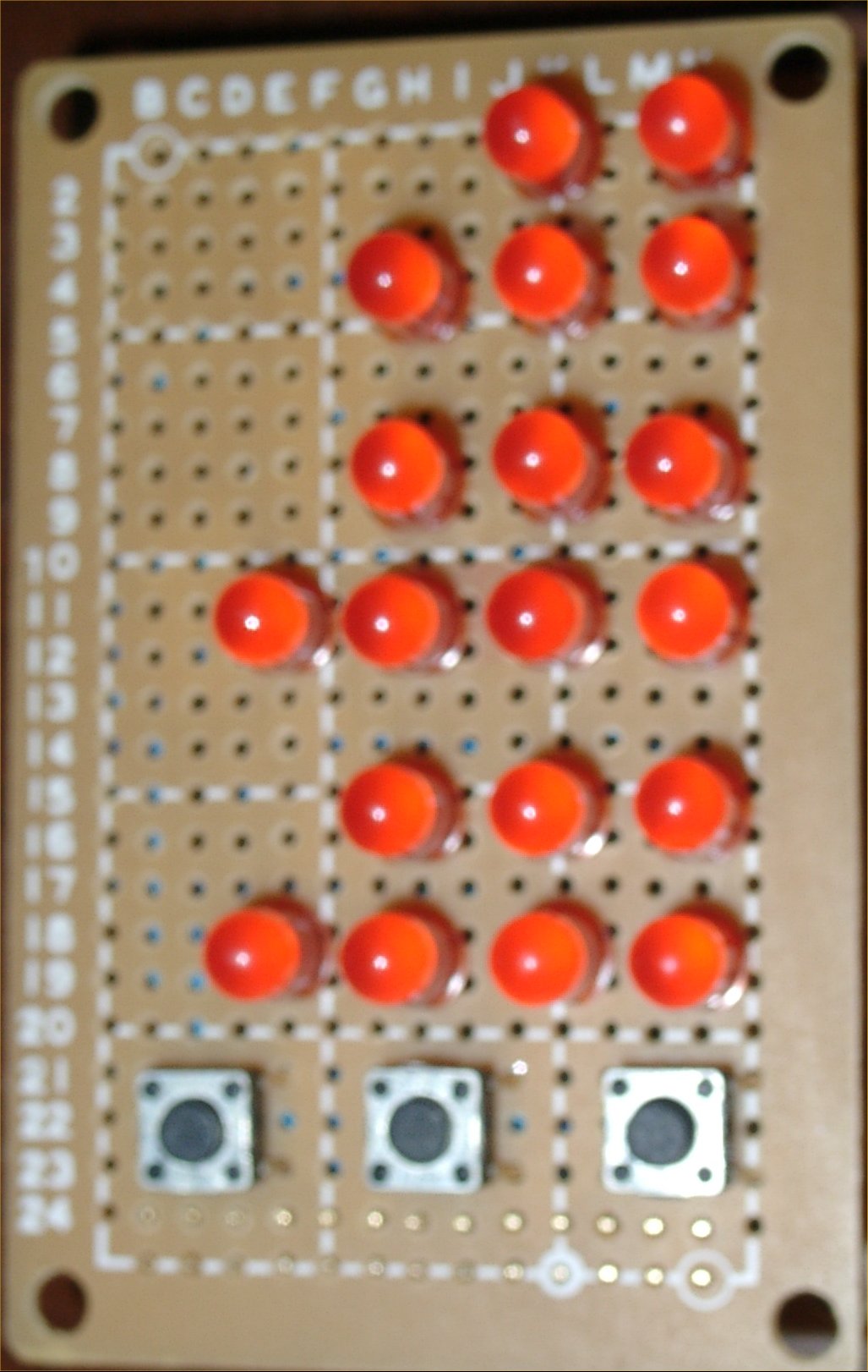
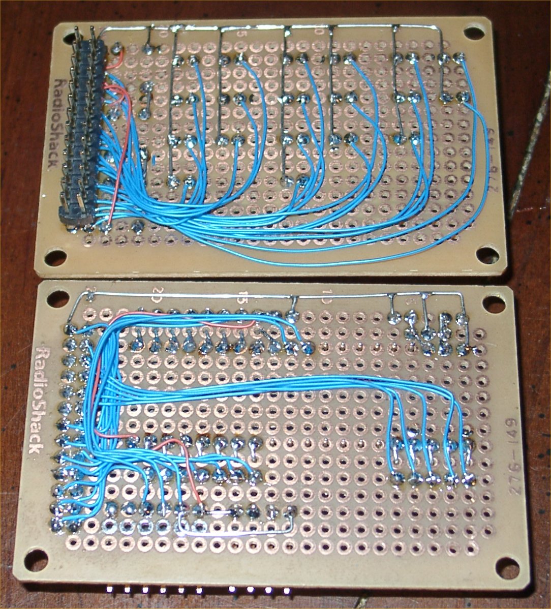
updated:
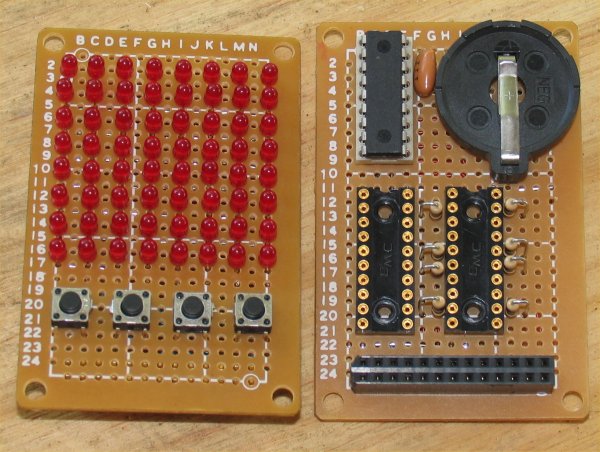
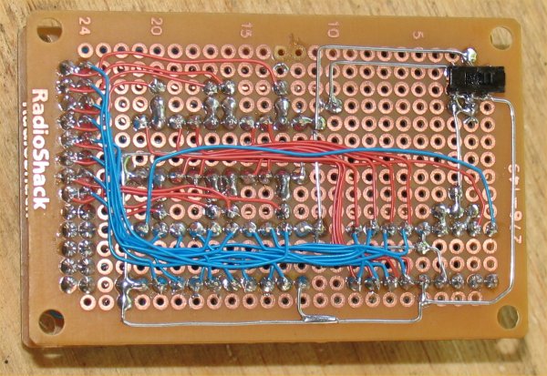
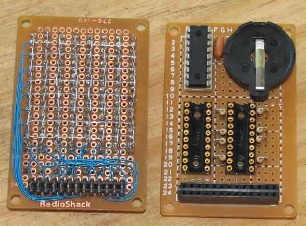
8-12-04
This is an 8x8 led light show
controlled by a pic 16f84a which
was modified from the version I found
on the web. I'm still waiting on my
driver chips to test it and to program
it, but will post code and pics later.
I will program my version with picc lite
instead of ASM as I don't know asm at
all and I guess I have no interest in learning
it either. I'll stick with C for now.
update:
8-11-04
I got my chips to find I wired the columns
backwards from the way I thought they
should be so everything was backwards.
I had to read the display using a mirror.
I spent several hours figuring out how to
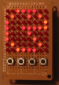
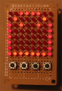
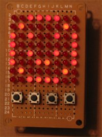
program this thing using PicC lite and was
able to successfully make a pacman, ghost,
smiley face and a colliding ball bounce to
start with. I'll upload the code as soon
as I can and if that isn't soon enough send
me an email and ask for it and I'll either try
to get it posted or just email it back to you.
update:
8-12-04
Added source of what I have so far. and
screenshots of some pictures.
circuit in action:
![]()
updated:
7-8-04
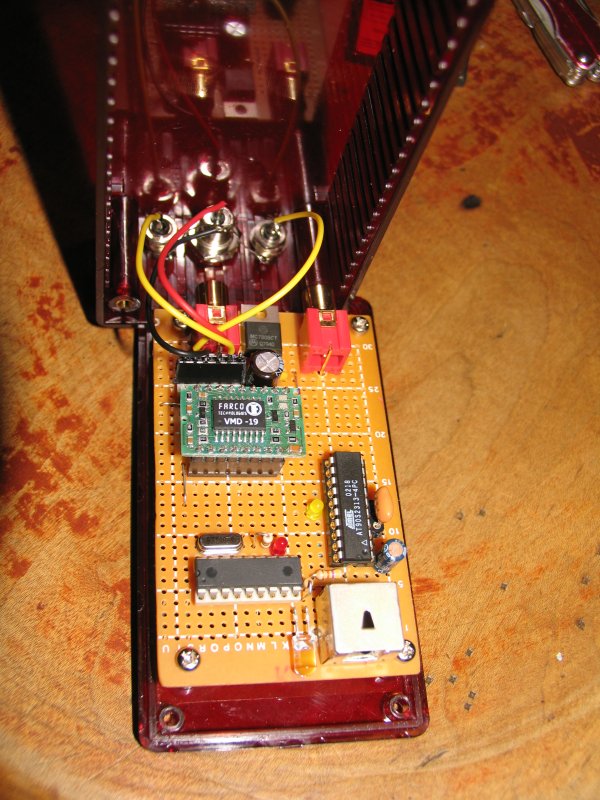
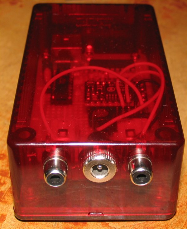
Learning remote chip
This is a test circuit I built that allows
you to learn 4 different remote control
commands and then play any of them
back. I plan to use this for a surveillance
circuit to start recording on a vcr without
rewiring the vcr. I plan to use the video
chip to sense motion, use an AVR or Pic to
control the learning remote and turn the
VCR on and start recording anytime there
is motion sensed. I may just use it for an
alarm type circuit, but I'm in the playing
mode right now. I bought the chip from
Dontronics if you are interested. I bought
the IRL-10 Remote Control Learner IC
and the VMD-19 Video Motion Detector IC if
you
care to check them out.
Picture
![]()
updated:
7-1-04
HeadBanger Amplifier
This is my version of the Headbanger headphone
amplifier I made for my Dell Digital DJ. With the
ear buds, it works great, but outputing to other stuff
is a bit weak. I built this pretty close to specs which
were very well written, but I didn't really follow the
directions except I took note of the ground separation
which I ran all my grounds to the battery ground and
the thing fired up the first time and works very well.
Pictures:
![]()
updated:
2-24-04
AVR binary clock (miniature)
I started making a miniature LED binary clock using
an AVR 8515. I have pictures of the circuit but have
no code available at this time. It has been put on hold
for the moment.
2-24-04: I got the basic functionality working and able
to keep track of time although it is off. I still need to
incorporate a free running 1second timer interupt to
get the code acurate. I'm using a 10mhz crystal right
now so keeping good time should be possible once I
get the timer working right. Not much luck so far.
I can send the code if anyone is interested or if you
are willing to work on the timer as I don't have
time right now for it.
I'm using 1 output per led and have 3 small buttons
for hold, slow and fast time set functions.
Update:
1-4-04
I coped out on this one so far. I can't seem to get
the 1 second timer working on the 8515 so I
opted to add the ELM440 freq chip to my clock
which has a 1 second output and a 60hz output
so I decided to use both. I use the 1 sec output
for the time and the 60hz output is used to clock
the leds so they flash at 60hz when enabled. I
checked the current this way and with about
13-15 leds on it draws around 50ma. I guess
I could go with a slower flash rate or longer time
off to get a lower current rate but I plan to use a
small transformer to power it with so I wasn't
concerned with power management. I just wanted
to build this thing and see if I could get it to work.
Here is the latest code I have which works just
fine for my clock.
update:
1-15-05
I cheated and added an ELM 440 chip to give me
my 1 second pulse and also used the 60hz pulse to
turn the LED's on so they don't load the chip down
by turning on so many of them. I checked the current
and it draws a max of ~51mA while running. I installed
the working unit inside a red case, added a cap to the
reset circuit and a big capacitor for backup which runs
the clock for 30sec if power is lost. I had fun with this
project and even though I couldn't get the timer to work
as planned, the clock works and is a nice addition to my
other clock. Here is a new picture of the finished
clock also.
schematic
![]()
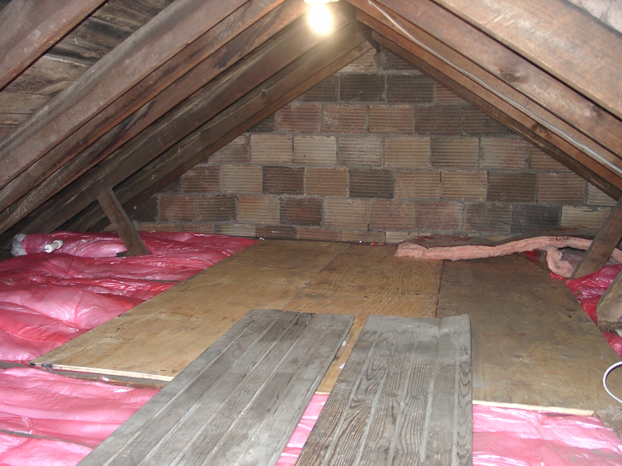
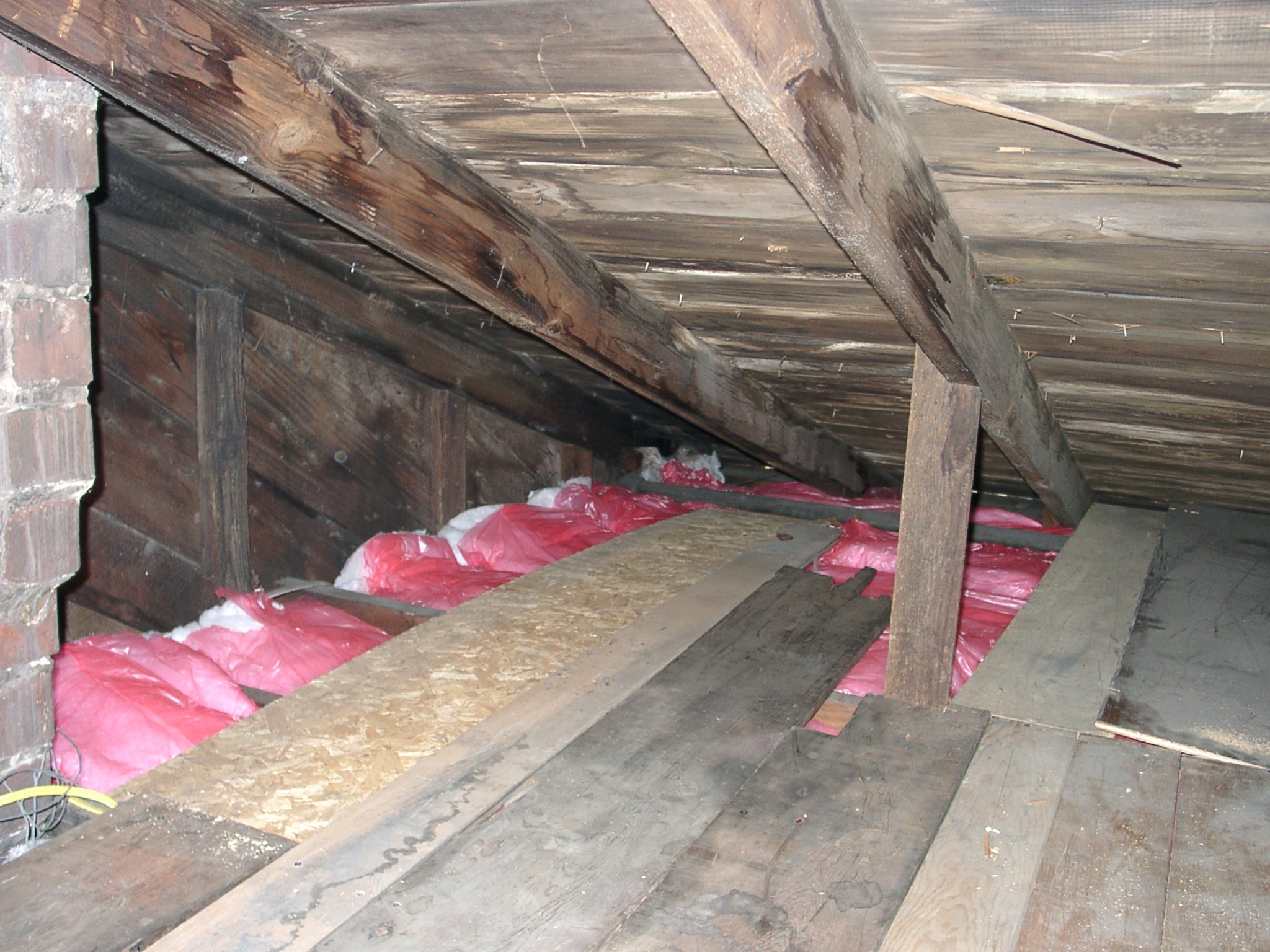
updated:
1-11-04
Insulate & install floor in attic
Not much fun here. But this is where I will have
pics of my project in the attic.
![]()
updated:
12-27-04
Directv DVR tivo hack
Ok, here is my info for my hacking experience
on upgrading my HDVR2 unit by Hughes. I
started out getting an HDVR2 unit with only
35 hours of record time for $217. I set it up and
played around with it a little to get the feel for
it. I then purchased a 200gig hard drive from
best buy for $229 before rebates and after
searching the internet and researching this
I ended up using this link for the cd iso
image that I needed for the command to
copy one drive to the other. I had 11.5gig
worth of stuff on my drive and it took
an hour and 4 minutes to make the copy.
I reinserted the drive back into the unit
and now the system says I have around 120
hours of record time! I did try to get a
unit from Circuit City already setup for
105 hours of record time for $450 which
didn't work out, so I ended up doing it
myself, got more record time and after
rebates it will be a good bit cheaper
also.
the command I used for the backup.....
mfsbackup -Tao - /dev/hdc | mfsrestore -s 127 -xzpi - /dev/hdd
my 40gig original drive was the master disk in the second ide
cable and the 160gig was the slave to that drive.
I'm trying to get serial bash to work but haven't been
very successful with it. Most things I found have been
tried and have failed, but I haven't given up just yet.
update:
1-11-04
I added another drive to my system. I now have 243
hours of record time. I started out with trouble
getting any listings for my season pass manager, but
after a day it fixed itself and made me happy.
HDVR2 pic
12-23-03
I upgraded my Mom's tivo for Christmas and now
she has 120 hours of record time. I also installed
a remote starter with keyless entry in her car but
that is another story.
12-27-04
I upgraded my Mom's tivo again fro Christmas this
year and now she has 243 hours of record time Like
I do.
![]()
updated:
5-21-03
status: work in progress
IRPD AVR 2313
This project uses a 2313-4 avr chip to control an IR
LED and a sharp ir receiver. I have basic functions
working so far, but got a long way to go. I only
have the source code available if someone wants
to get a jump start on coding their own circuit. I
found that I had to add a capacitor from the output
of the sharp receiver to ground to get a solid
signal into the 2313 to work right or it would just
sit there and blink when placing an object infront
of the sensor.
no pic available.
only prototype wired so far.
![]()
updated:
5-11-03
status: work in progress
Serial LCD Display
This project uses a 2313-10 avr chip to control a 16x2,
24x2,16x1,40x2 display depending on what is setup in
the source code prior to compiling. The display only
has minimal functionality right now. I used 8bit code
from one place and serial code from the SSC code I
used. I only modified them to work together. I have
functioning code to start at the top displaying the
input from the serial port and when it is filled it goes
to the bottom line and then back to the top for now.
I made a serial LCD interface so I can use either a
14 pin or 16 pin inline lcd display or a 14 pin dip
connection. I will upload the code and picture when I
can.
![]()
updated:
5-22-04
status: done?
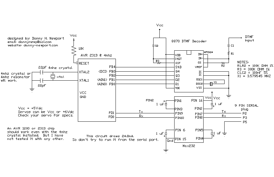
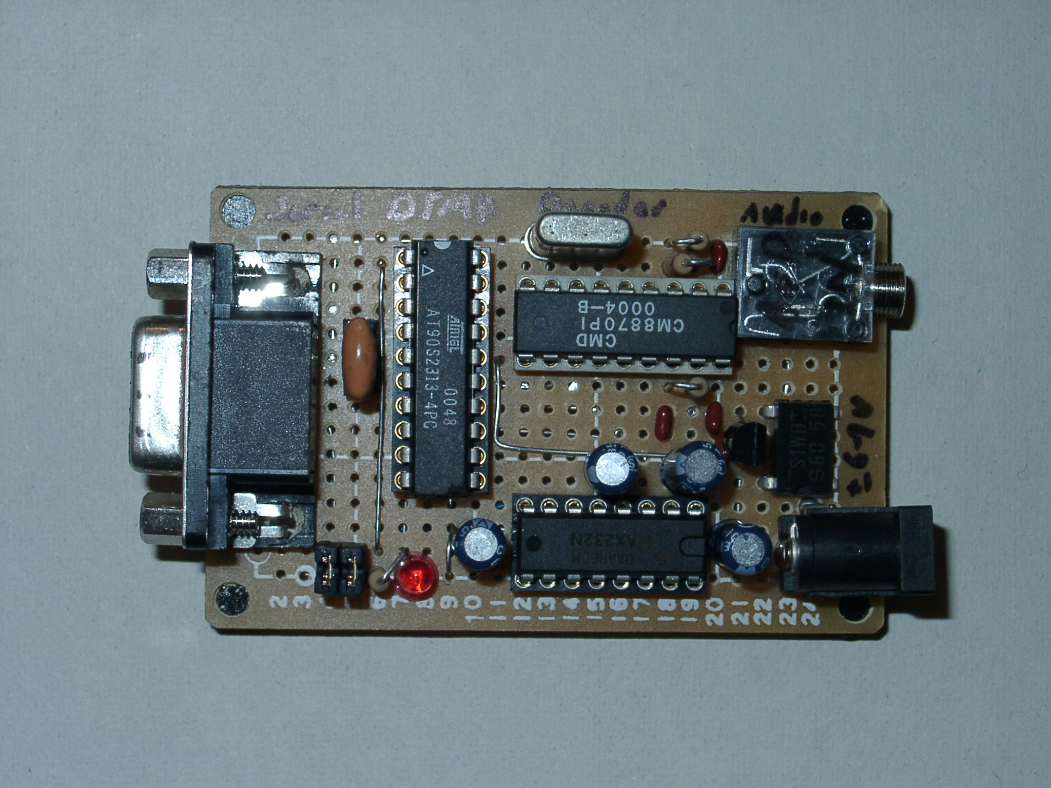
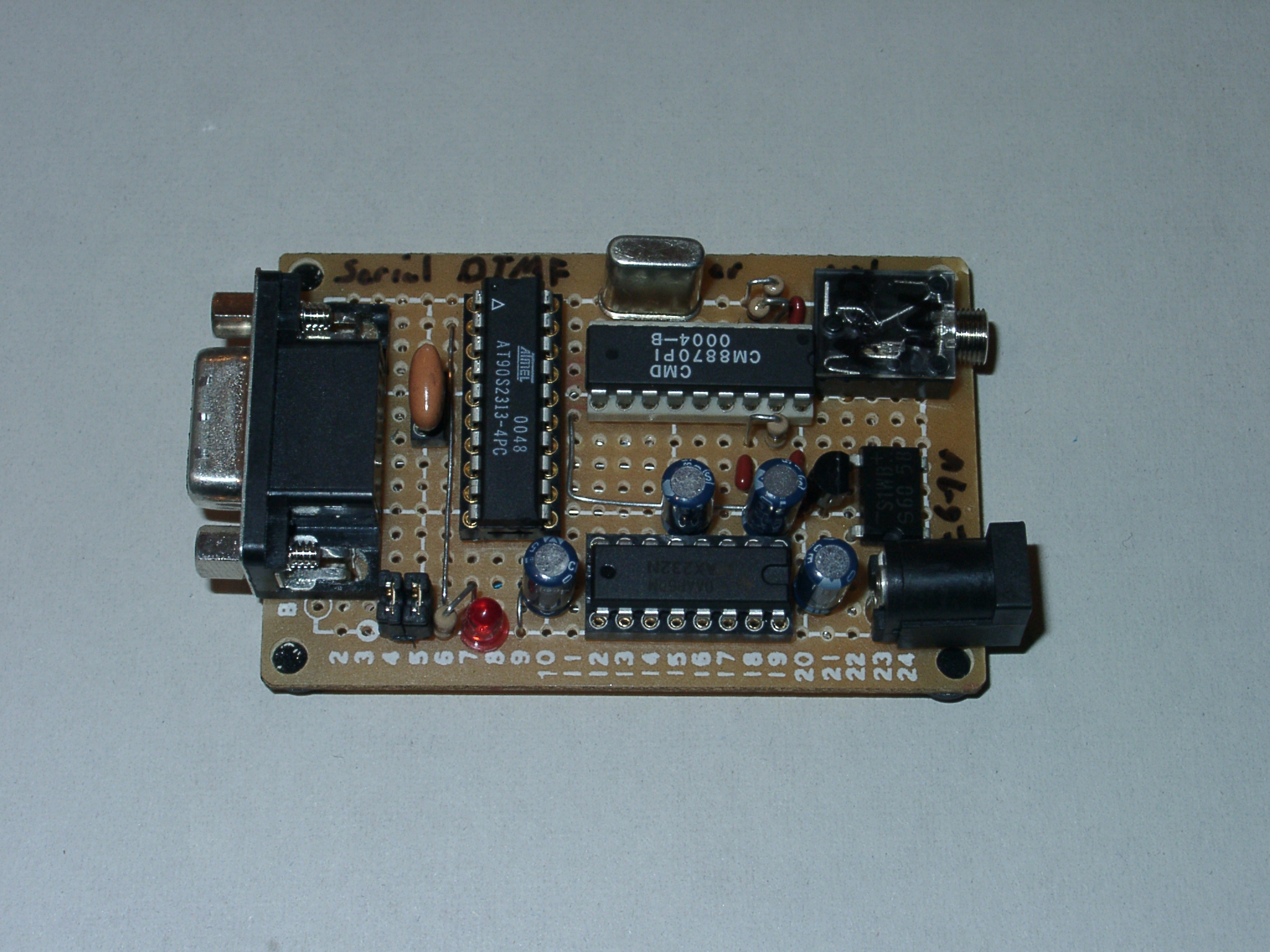
DTMF serial tone decoder
This project I'm working on will use an 8870 DTMF
tone decoder chip and a 2313 or 1200 to decode
the tones and send them to the serial line for
viewing. I only have the circuit for the 8870 chip
wired and no code yet, so this project may be a
while. But check back often for progress.
Update:
3-25-03
I have some basic functionality working on this.
I have it decoding the tones properly and after
2 seconds of inactivity it adds a space and after
15 seconds it adds a new line. I will be adding
more pictures and code once I have them. But
for now I only have the code which is fairly well
documented. Maybe even enough to get you
started. I only have a prototype setup now and
will be making a more permanent version
soon. Then the fine tuning will start. This
code is setup right now for the 2313 @ 4mhz
5-22-04:
Just added some pics.
(watch pinouts)
![]()
updated:
9-23-03
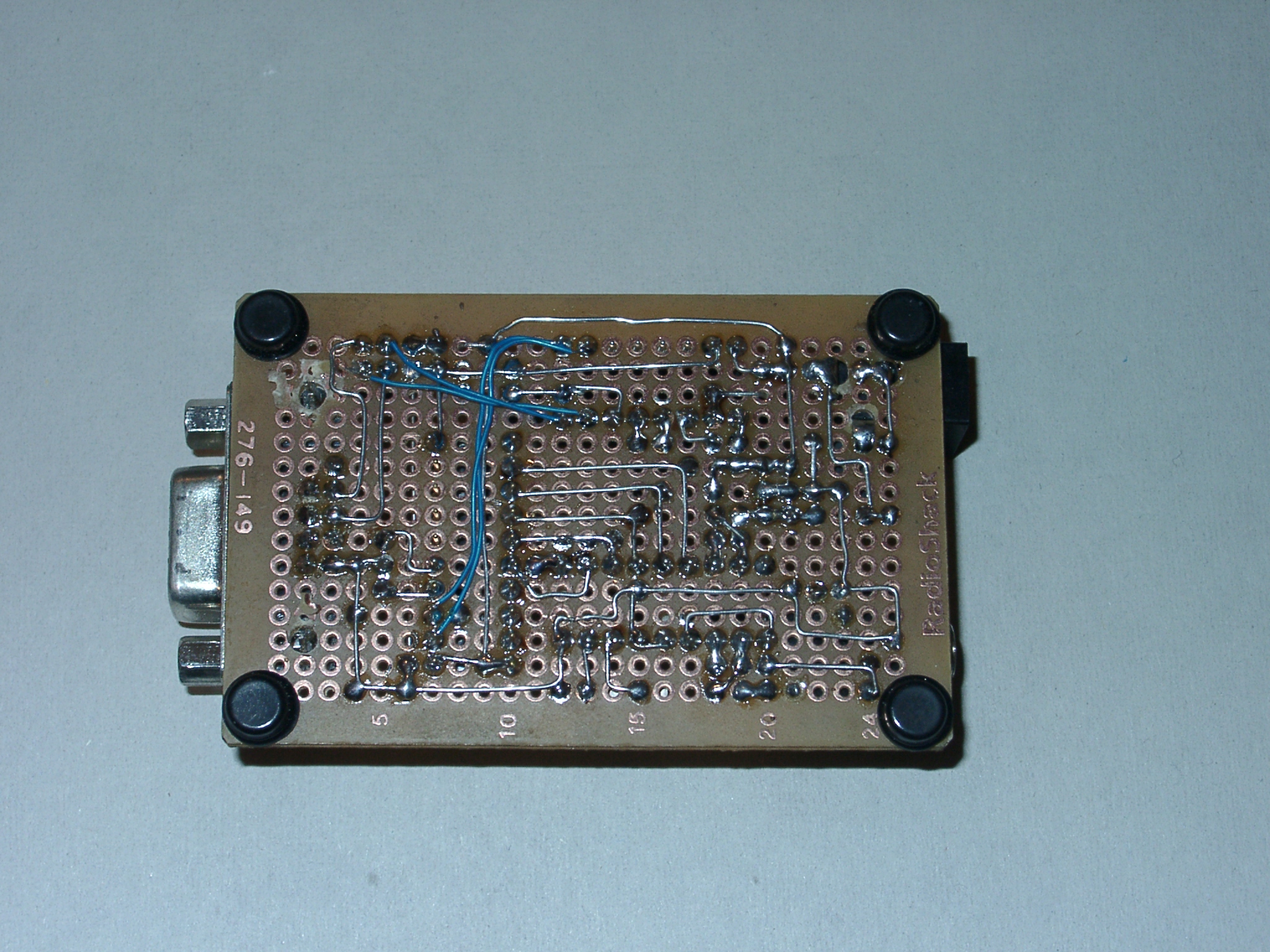
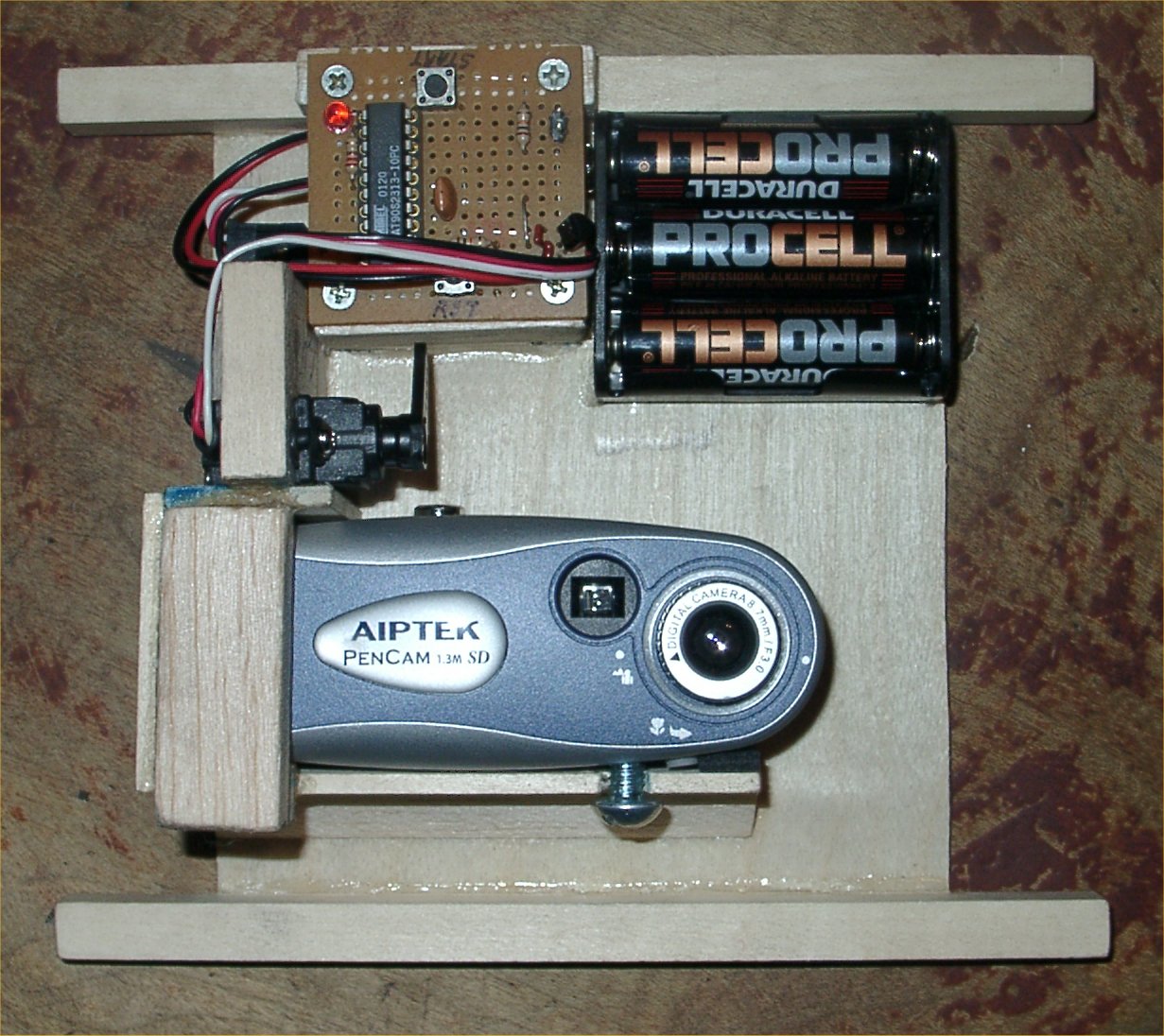
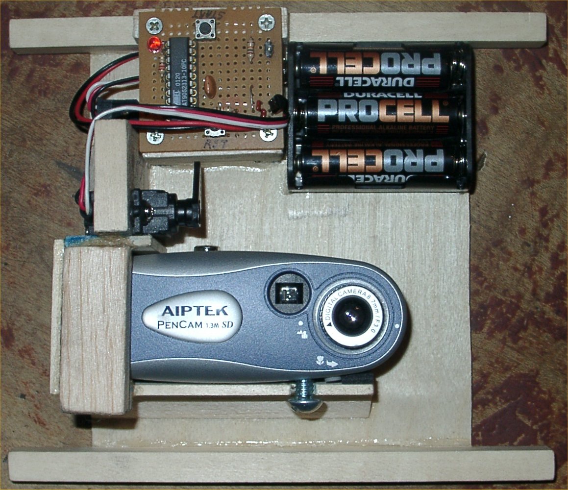
R/C servo onboard airplane camera control
status: done?
This project I'm working on will use a small r/c servo to
control the shutter on a small digital camera to be
installed onboard an r/c aircraft. I plan on putting a 3
minute timer to delay the taking of pictures. Then
about every 15seconds or whatever seems to be the
best time to take all the pictures during a flight. I don't
have any code to post or pictures to post, but the SSC
used on this page would be a good candidate to start.
I plan on using the AVR 1200 on the final product to cut
down on cost.
update:
4-23-03
I got my circuit and prototype of the controller done. I
got a 50 second delay for the first 3 pictures and then
18sec delay until all pics are taken. I can only take 13
pictures max without a memory card. The avr 2313
chip takes the picture and then backs off the shutter
a little and then turns off the servo to conserve power.
The source code has all the data needed to know how
to hook the circuit, if not, email me and I can tell you
how to wire it up or how it works if you need it.
update:
5-21-03
I found that a 128mb SD card gave me about 450-475
pictures so I have it shutoff after 475 pictures. That
gives me a 3-4 second delay between pictures and a
28 minute flight to get the card full and most of my
flights only last about 15minutes before I run out
of fuel. Pictures to follow after I get the new battery
installed and a clear day to go flying.
update:
6-8-03
I tested the camera on my airplane 6-1-03 and
it failed miserably. The shutter button never
got touched. Not sure why it didn't reach it
after all the testing I did, but it shouldn't do
it anymore after the program update I did.
I added a configuration function to the program
to allow field adjustment of the shutter control.
The arm of the servo cycles back and forth
moving towards the shutter each time until
the user presses the button to stop it and
the unit will be configured. Then press the
same button to start taking pictures. I hope
it will work next time.
update:
6-11-03
I added a windows program to test the
serial servo board. Check it out under
my windows section of my programs.
update:
4-1-04
Fixed broken link to RCcam50.rom
*rom for 50 pics*
source w/ 4 roms
source w/ roms & for 475 pics
updated version:
![]()
updated:
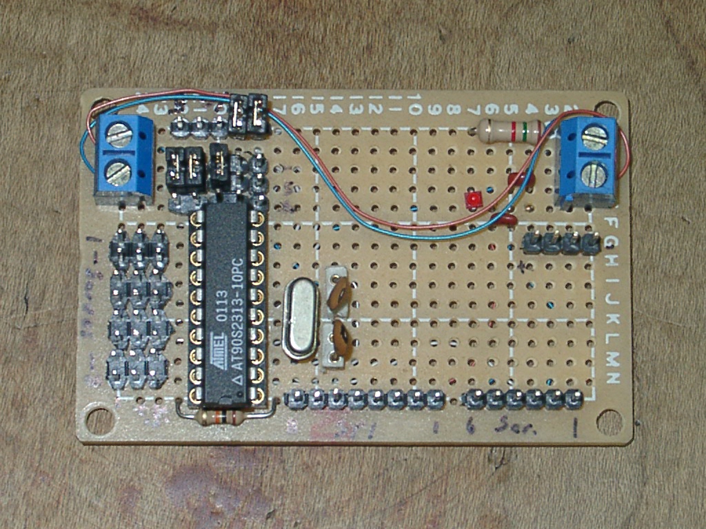
3-21-03
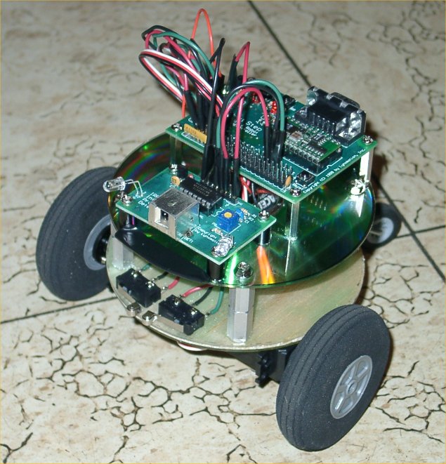
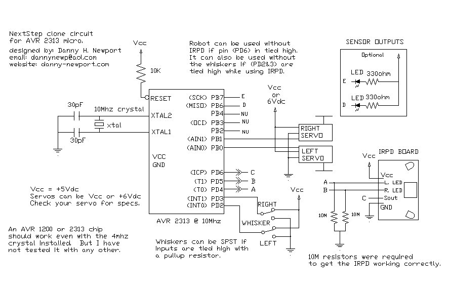
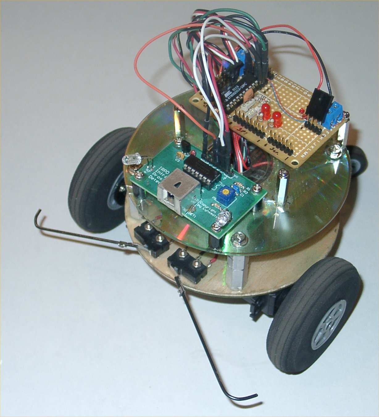
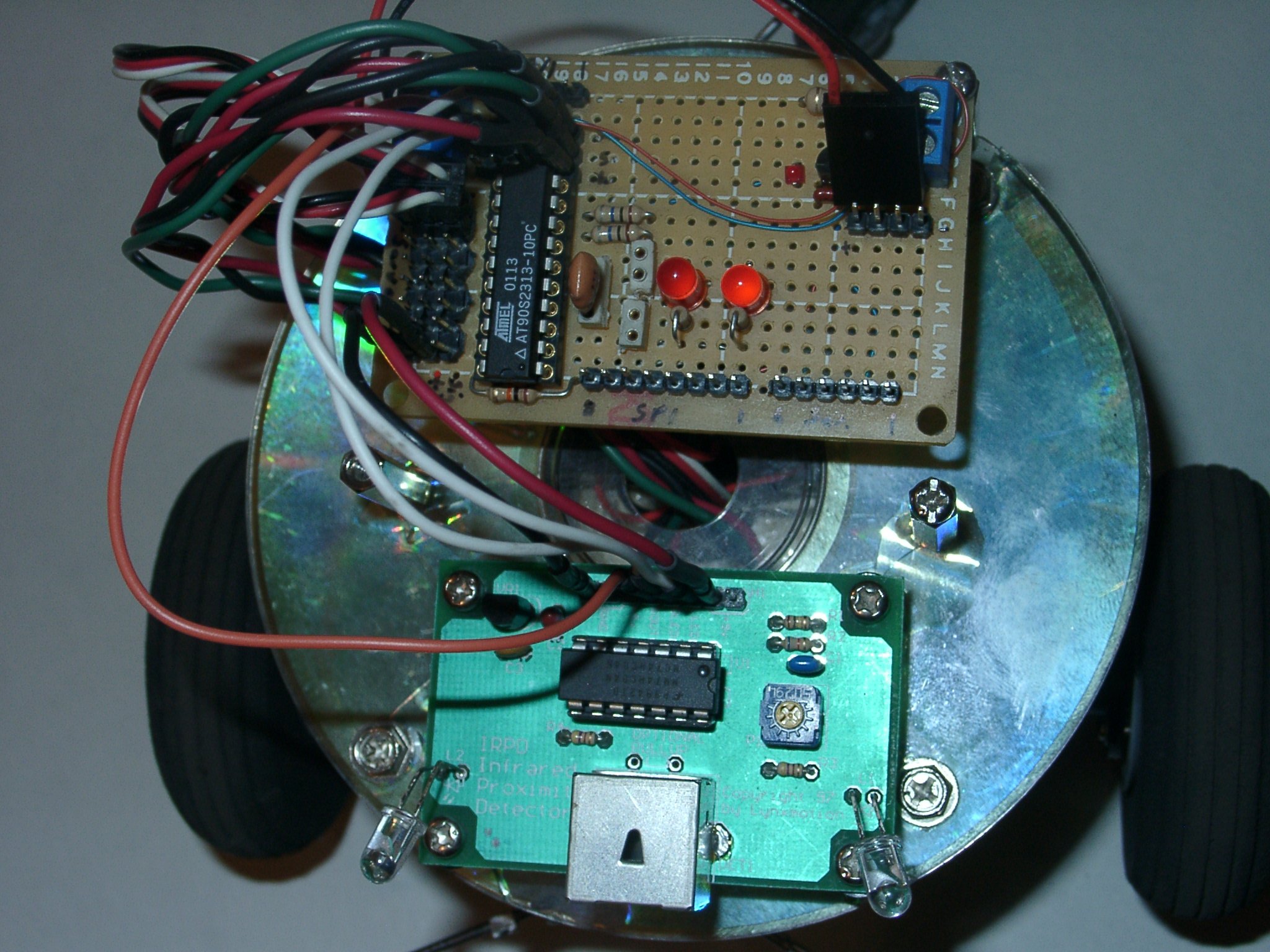
NextStep clone with avr 2313
version 1.3
status: done?
This is a picture of my new robot controller. I started with
code from a SSC from here. I modified it to work as a
NextStep clone for my FirstBot robot. I have a basic
functioning robot using the new chip and whisker switches.
I'm working on getting the IRPD working next.
I will post the source code once I have it working with
more pictures and schematics. I'll try to keep my source
code well documented also. I am using gcc and
avredit to compile my program and downloading it with
wppisp and my wppispgui located on my site.
Update:
3-14-03:
I got the IRPD working. It wasn't a timing issue. I needed
to put a 10M ohm resistor between the LED pin and gnd
to fix the problem. My O-scope showed a bad waveform
and the resistor seemed to make things work great. I
even worked on the whisker switch logic a bit so the
robot will backup a little before turning so it doesn't
turn into what it just bumped into. The source code includes
the rom and all files created by the AvrEdit program. I'm
using a delay_ms() routine for my timing. I will upload
new pictures and schematic once created. The source
code is pretty much all you need to get started on how
things are hooked up.
3-21-03:
v1.3 - I added code to keep the robot from getting stuck.
I found the 1.2 version would run toward a corner and if
angled right, it would just shack back and forth. So I
added some code to keep track of the number of
cycles the motion is and if forward motion isn't found
within 6 cycles, then it adds some time to the turning
of the robot to help get it out of the cycle.
source code(v1.2)
source code(v1.3)
2313 rom only(v1.2)
2313 rom only(v1.3)
avr2313(pic)
avr2313(new)
avr2313(closup)
![]()
updated:
2-14-03
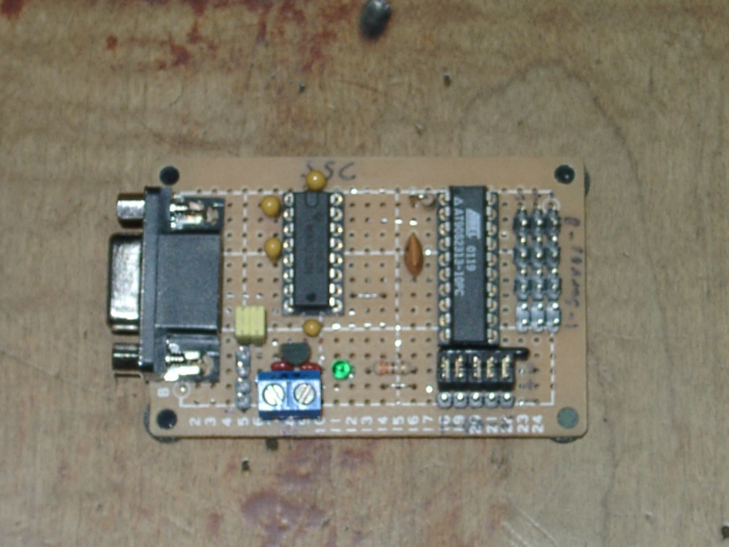
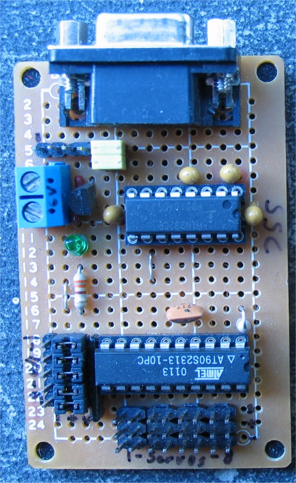
SSC with avr 2313
status: done
This is a picture of my finished serial servo controller (ssc)
that I made with an AVR 2313 using code from here.
This rom is the one I used in my chip from the
code I downloaded after I had to fix a few typos.
You can download it here without the need
to compile the program. You can use wppisp and my
wppispgui to download it to the chip if you want. I named
my file servo2 after modifying it. The Modification which
is documented in the source code allows serial
commands to just read each general purpose IO
and return 0 if the pin is low and 1 if the pin is high.
All the other commands are there from the original source
code and works unmodified, so my rom is a replacement
for the original with some added features. I compiled
the source with avredit.
I use pwm from 20 to 70 to get the servo to rotate
90 degrees left and 90 degrees right without messing
up the servo by driving it too far.
SSC2313.rom(original rom)
Servo2.rom(modified)
![]()
Hit Counter:
![]()
22000:4-14-06
.bmp)